Rating:
Information pump assy, supply Denso
Product
Fuel Injection Pump
Vehicle engine
L200/TRITON 4D56
Engine
4D56
Serial start-end
1412-
Info
Injector Nozzle
MITSUBISHI
PUMP ASSY, SUPPLY
EA
- *1 SIAM DENSO PRODUCTION SM294000-235#
Compare Prices: .
As an associate, we earn commssions on qualifying purchases through the links below

Fuel Injection Pump Compatible with Mitsubishi L200 Engine 4D56 1460A097 294000-1370 2940001370
KoovDem Part Number: 1460A097 294000-1370 2940001370 Note: Please check the fitment carefully before purchase. Or just tell us the part number you need. || Part Name: Fuel Injection Pump || The 4D56 engine is a reliable and fuel-efficient 2.5-liter diesel engine used in Mitsubishi vehicles. It provides adequate power for city driving and long-distance travel, with a focus on durability and longevity. Popular in pickups, SUVs, and commercial vehicles, the 4D56 engine offers a balance of performance and efficiency. It is a dependable choice for many manufacturers. || Designed specifically for the Mitsubishi L200 Engine 4D56, this product guarantees a perfect fit and superior performance. It is suitable for a wide range of applications, offering reliability and efficiency. Easy to install and operate, this product is the ideal choice for maintaining or upgrading your engine. || Included in the package is one piece of the Fuel Injection Pump with part numbers 1460A097, 294000-1370, and 2940001370.
KoovDem Part Number: 1460A097 294000-1370 2940001370 Note: Please check the fitment carefully before purchase. Or just tell us the part number you need. || Part Name: Fuel Injection Pump || The 4D56 engine is a reliable and fuel-efficient 2.5-liter diesel engine used in Mitsubishi vehicles. It provides adequate power for city driving and long-distance travel, with a focus on durability and longevity. Popular in pickups, SUVs, and commercial vehicles, the 4D56 engine offers a balance of performance and efficiency. It is a dependable choice for many manufacturers. || Designed specifically for the Mitsubishi L200 Engine 4D56, this product guarantees a perfect fit and superior performance. It is suitable for a wide range of applications, offering reliability and efficiency. Easy to install and operate, this product is the ideal choice for maintaining or upgrading your engine. || Included in the package is one piece of the Fuel Injection Pump with part numbers 1460A097, 294000-1370, and 2940001370.

Diesel Fuel Injection Pump 294000-1240 1460A001 1460A047 1460A057 1460A097 Compatible For MITSUBISHI 4D56 TRITON Compatible For CHALLENGER
UCLMCNID Made of high-performance alloys, it is wear-resistant and corrosion-resistant, extending its service life. || Using our product can fully atomize fuel, promote complete combustion, and improve fuel economy. || The internal fuel flow channel has been optimized to reduce pressure loss. || It can maintain a stable working state under various working conditions. || Diesel Fuel Injection Pump 294000-1240 1460A001 1460A047 1460A057 1460A097 Compatible For MITSUBISHI 4D56 TRITON Compatible For CHALLENGER
UCLMCNID Made of high-performance alloys, it is wear-resistant and corrosion-resistant, extending its service life. || Using our product can fully atomize fuel, promote complete combustion, and improve fuel economy. || The internal fuel flow channel has been optimized to reduce pressure loss. || It can maintain a stable working state under various working conditions. || Diesel Fuel Injection Pump 294000-1240 1460A001 1460A047 1460A057 1460A097 Compatible For MITSUBISHI 4D56 TRITON Compatible For CHALLENGER

Worldthump Fuel Pump, OE 294000-2350 2940002350 1460A097 1pc Engine Fuel Injection Pump Replacement for Mitsubishi Pajero Triton L200 4D56
Worldthump Part Number: OE Number for Reference: 294000-2350, 1460A097, 294000-2321, 22100-30161. Please carefully check whether the product's part number is consistent with your vehicle. || Fitment Vehicles: Fuel injection pump is replacement for Mitsubishi Engine 4D56 Truck Pajero Triton L200. To avoid unnecessary returns, please confirm the product's adaptation information before placing an order. || Premium Materials: The fuel pump is made of high-quality metal materials, with a solid structure, high strength, impact resistance, not easy to damage, high temperature resistance, not easy to rust, and long service life. || Excellent Performance: The Engine fuel pump has been professionally designed and tested, with excellent performance and high reliability. It can accurately deliver fuel to the engine and keep the engine running efficiently || Direct Replacement: Fuel injection pump is produced with original specifications and can directly replace the old or damaged one, without modification and complicated operations, saving your time.
Worldthump Part Number: OE Number for Reference: 294000-2350, 1460A097, 294000-2321, 22100-30161. Please carefully check whether the product's part number is consistent with your vehicle. || Fitment Vehicles: Fuel injection pump is replacement for Mitsubishi Engine 4D56 Truck Pajero Triton L200. To avoid unnecessary returns, please confirm the product's adaptation information before placing an order. || Premium Materials: The fuel pump is made of high-quality metal materials, with a solid structure, high strength, impact resistance, not easy to damage, high temperature resistance, not easy to rust, and long service life. || Excellent Performance: The Engine fuel pump has been professionally designed and tested, with excellent performance and high reliability. It can accurately deliver fuel to the engine and keep the engine running efficiently || Direct Replacement: Fuel injection pump is produced with original specifications and can directly replace the old or damaged one, without modification and complicated operations, saving your time.
You can buy:

Components :
Scheme #.#:
№
Qty
Part num
Name
Remarks
Manufacture num
000
[01]
29400-02350
PUMP ASSY, SUPPLY
1460A097
MITSUBISHI
Include in ##:
29400-02350
as PUMP ASSY, SUPPLY
Cross reference number
Part num
Firm num
Firm
Name
29400-02350
1460A097
MITSUBISHI
PUMP ASSY, SUPPLY
2940002350
1460A097
MITSUBISHI
PUMP ASSY, SUPPLY
Information:
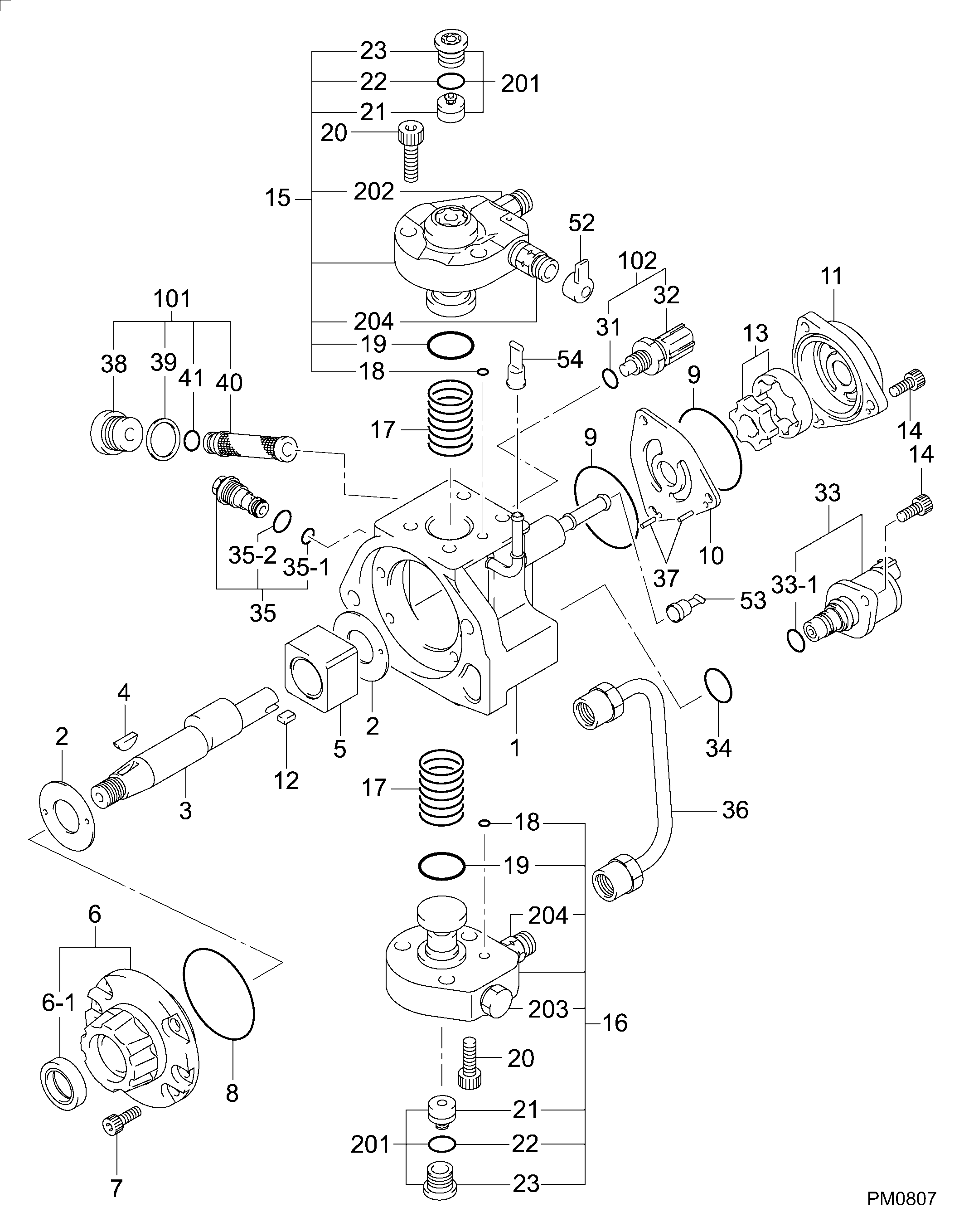
1. Disconnect pressure line (3). Remove two bolts (2).2. Move fuel ratio control (1) up to disengage the fuel ratio control from the lever assembly in the governor. 3. Remove four O-ring seals (4) and screen assembly (5). The following steps are to install the fuel ratio control.4. Inspect, replace and install the four O-ring seals (4) and the screen assembly (5).5. Put the fuel ratio control (1) in position and engage the fuel ratio control with the lever assembly in the governor.6. Install the bolts that hold the fuel ratio control and connect pressure line (3) to the fuel ratio control (1). See Testing And Adjusting for Fuel Ratio Control Adjustment procedure.Disassemble And Assemble Fuel Ratio Control
Start By:a. remove fuel ratio control
Keep all parts clean from contaminants. Contaminants put into the system may cause rapid wear and shortened component life.
1. Remove the two bolts, and the fuel ratio control. Remove O-ring seal (1). 2. Put tooling (A) in a vise as shown so that the station being used is not over the vise jaw. Place the fuel ratio control over the pins in tooling (A). Remove cover (2) and the gasket.
There is spring force behind cover (3). Hold cover (3) in position, and slowly remove the bolts that hold it to release the spring force.
3. Remove cover (3). 4. Remove nut (5) and stop (6). 5. Remove spring (9), washer (7), and diaphragm (10) from retainer (8). Remove retainer (8) from housing (11). 6. Remove nut (16) from extension (15), and remove the extension from retainer (8). Remove valve (12), spring (13) and O-ring seal (14). 7. Remove spring (18), retainer (17) and spring (19). 8. Remove piston assembly (20). 9. Use tooling (B), and remove snap ring (21) and the wave washers from valve assembly (22). Remove piston assembly (23). Remove seal (24). 10. If necessary, remove stem (26) from valve (25).11. Clean and inspect all parts. Make a replacement of all parts that are worn or damaged. The following steps are to assemble the fuel ratio control.12. Assemble stem (26) to valve (25) using 9S3265 Retaining Compound.13. Put seal (24) on piston (23). Install piston (23) on valve assembly (22).14. Put two wave washers in position on valve (22). Use tooling (B) to install the snap ring on the valve assembly.15. Place housing (4) on tooling (A), and put tooling (C) into the bore of the housing. Lubricate tooling (C) with clean engine oil.16. Put a small amount of clean oil on the seal of the piston assembly, and push piston assembly (23) into position with a smooth swift motion.17. Place spring (9), retainer (17) and spring (19) in position in housing (4).18. Put O-ring seal (14) on extension (15). Put spring (13) and valve (12) in position on the extension.19. Lubricate O-ring seal (14) with clean engine oil. Install extension (15) in retainer (8). Install nut (16).20. Put diaphragm (10), washer (7) and spring (9) in position on retainer (8). Install retainer (8).21.