Rating:
Information pump assy, supply Denso
Product
Fuel Injection Pump
Vehicle engine
INDUSTRIAL V3800DI
Engine
V3800DI
Serial start-end
1111-
Info
Injector Nozzle
Compare Prices: .
As an associate, we earn commssions on qualifying purchases through the links below

1J500-50500 Fuel Injection Pump for Kubota Engine V3800 Tractor M8560 Loader SVL90-2 Fuel Pump Ass'y Replacement Parts 294000-1720 294000-1730
Podafu Part Number: 294000-1720 1J500-50501 294000-1721 294000-172# 294000-1730 294000-173# 1J500-50500 Fuel Injection Pump, Fuel Pump || Application: Fit for Kubota Engine V3800, Tractor M4N-071HD12 M4N-071HDC12 M4N-071HDRC12 M8560, Compact Track Loader SVL90-2. || Perfect Replacement: Crafted from premium materials and meticulously engineered, tailored for specific vehicles. Rigorously tested for leaks and longevity. Easy and quick to install as a seamless replacement. || Make sure to confirm the part number and vehicle model to ensure that the product is compatible with your specific requirements. || By reducing fuel consumption, improving jitter, and enhancing speed smoothness, driving becomes more comfortable while also decreasing monthly fuel expenses.
Podafu Part Number: 294000-1720 1J500-50501 294000-1721 294000-172# 294000-1730 294000-173# 1J500-50500 Fuel Injection Pump, Fuel Pump || Application: Fit for Kubota Engine V3800, Tractor M4N-071HD12 M4N-071HDC12 M4N-071HDRC12 M8560, Compact Track Loader SVL90-2. || Perfect Replacement: Crafted from premium materials and meticulously engineered, tailored for specific vehicles. Rigorously tested for leaks and longevity. Easy and quick to install as a seamless replacement. || Make sure to confirm the part number and vehicle model to ensure that the product is compatible with your specific requirements. || By reducing fuel consumption, improving jitter, and enhancing speed smoothness, driving becomes more comfortable while also decreasing monthly fuel expenses.

Otobaijeni 1J500-50501 294000-1720 294000-1730 1J500-50500 Fuel Injection Pump for Kubota Engine V3800 Tractor M8560 Loader SVL90-2 Fuel Pump Ass'y Replacement Parts
otobaijeni Part Number: 294000-1720 1J500-50501 294000-1721 294000-172# 294000-1730 294000-173# 1J500-50500 Fuel Injection Pump, Fuel Pump || Application: Fit for Kubota Engine V3800, Tractor M4N-071HD12 M4N-071HDC12 M4N-071HDRC12 M8560, Compact Track Loader SVL90-2. || Ideal Replacement: Made with high-quality materials and precision-designed, suitable for specific vehicles. Professionally aged and leak-tested to ensure durability. Quick and effortless installation through replacement. || Ensure Fitment: Please check the part number and vehicle model to ensure the product fits your needs. || Reduce fuel consumption, improve jitter, and speed up smoothness, You can drive in comfort and reduce your monthly fuel costs.
otobaijeni Part Number: 294000-1720 1J500-50501 294000-1721 294000-172# 294000-1730 294000-173# 1J500-50500 Fuel Injection Pump, Fuel Pump || Application: Fit for Kubota Engine V3800, Tractor M4N-071HD12 M4N-071HDC12 M4N-071HDRC12 M8560, Compact Track Loader SVL90-2. || Ideal Replacement: Made with high-quality materials and precision-designed, suitable for specific vehicles. Professionally aged and leak-tested to ensure durability. Quick and effortless installation through replacement. || Ensure Fitment: Please check the part number and vehicle model to ensure the product fits your needs. || Reduce fuel consumption, improve jitter, and speed up smoothness, You can drive in comfort and reduce your monthly fuel costs.

SINOCMP 1J500-50501 294000-1720 294000-1730 Fuel Injection Pump for Kubota V3800 V3800DI Diesel Engine
SINOCMP 【Accurate】installation and use our excavator parts. Please find the suitable product based on the old part number and machine model. || 【Scientific】products pass professional testing and inspection. Not sure what the construction machinery product will do? The adaptable products, safe using operation and easy installation. || 【Use】construction machinery product must be in accordance with operating procedures to avoid accidents. We will provide matching product usage guidance and professional product operation suggestions. || 【Key】construction machinery equipment meaning of existence? It is to bring convenience to life. In order to avoid the trouble of frequent replacement, strictly require product quality and improve service life.
SINOCMP 【Accurate】installation and use our excavator parts. Please find the suitable product based on the old part number and machine model. || 【Scientific】products pass professional testing and inspection. Not sure what the construction machinery product will do? The adaptable products, safe using operation and easy installation. || 【Use】construction machinery product must be in accordance with operating procedures to avoid accidents. We will provide matching product usage guidance and professional product operation suggestions. || 【Key】construction machinery equipment meaning of existence? It is to bring convenience to life. In order to avoid the trouble of frequent replacement, strictly require product quality and improve service life.
Components :
Scheme #.#:
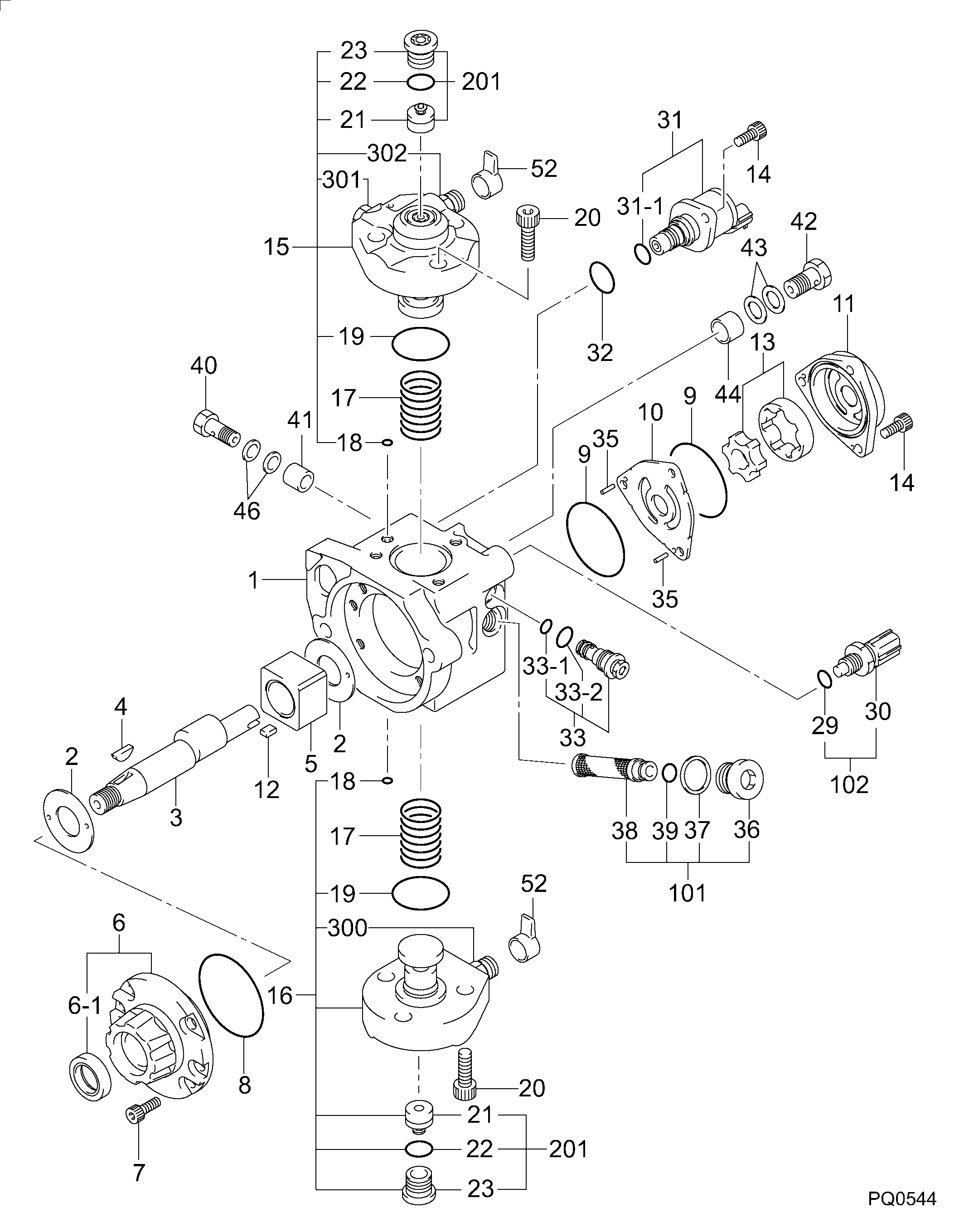
№
Qty
Part num
Name
Remarks
Manufacture num
000
[01]
29400-01720
PUMP ASSY, SUPPLY
HP3
1J500-50501
KUBOTA
Include in ##:
29400-01720
as PUMP ASSY, SUPPLY
Cross reference number
Part num
Firm num
Firm
Name
29400-01720
1J500-5050
PUMP ASSY, SUPPLY
2940001720
1J500-50501
KUBOTA
PUMP ASSY, SUPPLY
2940001720
1J500-50502
KUBOTA
PUMP ASSY, SUPPLY
2940001720
1J500-50503
KUBOTA
PUMP ASSY, SUPPLY
2940001720
1J500-50504
KUBOTA
PUMP ASSY, SUPPLY
2940001720
1J500-50505
KUBOTA
PUMP ASSY, SUPPLY
Information:
Start By:a. remove governor**See Disassemble Governor story
Keep all parts clean from contaminants. Contaminants put into the system may cause rapid wear and shortened component life.
1. Remove the bolts and the plate from the side of the fuel injection pump housing. 2. Install tool (A) in the fuel injection pump housing. Move the rack until tool (A) can be installed to hold the rack in the center position to remove the fuel injection pumps.3. Use tool (B) to remove bushing (1).4. Remove the O-ring seal from the fuel injection pump housing. 5. Install tool (C) on the bonnet and remove the fuel injection pump. 6. Remove spacer (2). Keep the spacers (2) from the fuel injection pumps together with identification as to their location in the pump housing.7. Perform steps 3 through 6 to remove the other fuel injection pumps. The following steps are to install the fuel injection pumps.8. Install spacer (2).9. Install tool (A). Move the rack until tool (A) can be installed to hold the rack in the center position. The rack must be in the center position to install the fuel injection pumps.10. Turn camshaft until the lobe of the camshaft is down for the pump to be installed.11. Install tool (C) on the bonnet on the fuel injection pump.12. Install the fuel injection pump in the pump housing with saw cut slot in the gear in alignment with the small pin and groove in the barrel in alignment with dowel in the pump housing.13. Put clean oil on O-ring seal and install it in the fuel injection pump housing.14. Install the bushing by hand until the bushing is even with the top of the housing. If the bushing can not be installed this far by hand, remove it. Remove the fuel injection pump ad put the pump in alignment again and install the bushing again.15. Install tool (B) on the bushing and tighten the bushing to a torque of 190 14 N m (140 10 lb ft).16. Install tooling (D) to measure total rack travel. Correct rack travel is 15.7 mm (.618 in). A smaller measurement is an indication of improper fuel injection pump installation.17. Perform Steps 1 through 9 to install the other fuel pumps18. Install the cover and gasket on the fuel injection pump housing.End By:a. install governor**See Assemble Governor storyDisassemble And Assemble Fuel Injection Pumps
Start By:a. remove fuel injection pumps
When the injection pumps are disassembled, handle the parts carefully. Do not damage the surfaces of the plungers, barrels and bonnets. Any scratches will cause leakage inside the fuel injection pump. The plunger and barrel for each pump are made as a set. Do not intermix the plunger of one pump in the barrel with another pump. If one part is worn, install a complete new pump assembly. Be careful when placing the plunger into the bore of the barrel.
1. Pull plunger (1) and washer (5) out of barrel (3) and spring (2).
Do not remove the gear from the plunger.