Rating:
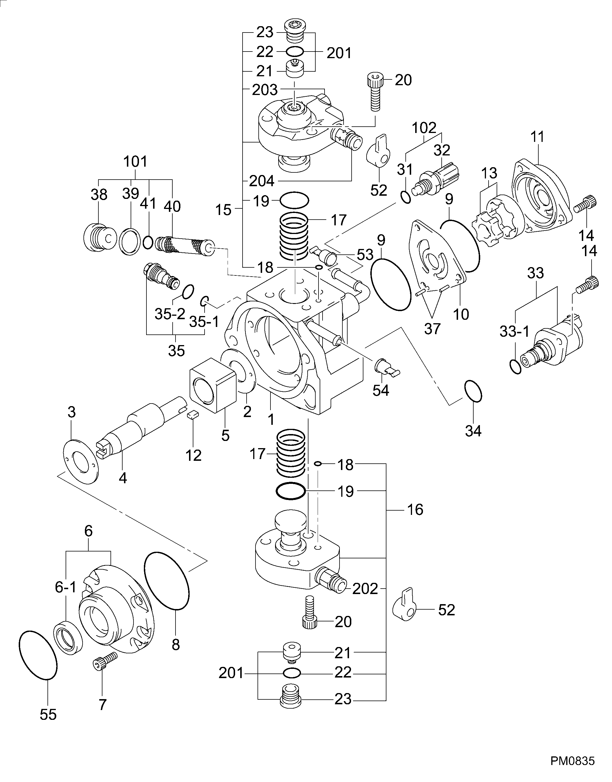
Information pump assy, supply Denso
Compare Prices: .
As an associate, we earn commssions on qualifying purchases through the links below

Compatible with Mitsubishi Diesel Engine 4N13 Fuel Injection Pump 1460A043 294000-0990
KoovDem Part Number: 1460A043 294000-0990 Note: Please check the fitment carefully before purchase. Or just tell us the part number you need. || Part Name: Fuel Injection Pump || The 4N13 engine is a reliable and high-performing four-cylinder engine with advanced technology like turbocharging and direct injection, providing impressive power and efficiency. Its compact and lightweight design makes it suitable for various vehicles, offering a smooth driving experience and fuel efficiency. Overall, the 4N13 engine is a great choice for any automotive needs. || Suitable for use with Mitsubishi Diesel Engine 4N13. || Package includes: 1 piece of Fuel Injection Pump 1460A043 294000-0990.
KoovDem Part Number: 1460A043 294000-0990 Note: Please check the fitment carefully before purchase. Or just tell us the part number you need. || Part Name: Fuel Injection Pump || The 4N13 engine is a reliable and high-performing four-cylinder engine with advanced technology like turbocharging and direct injection, providing impressive power and efficiency. Its compact and lightweight design makes it suitable for various vehicles, offering a smooth driving experience and fuel efficiency. Overall, the 4N13 engine is a great choice for any automotive needs. || Suitable for use with Mitsubishi Diesel Engine 4N13. || Package includes: 1 piece of Fuel Injection Pump 1460A043 294000-0990.

IMIFAFTAbT 1460A036 1460A043 294000-0990 l294000-0991 Fuel injection pump Fits for Mitsubishi Lancer ASX 4N13 Engine 1.8 DI-D
IMIFAFTAbT Product Name: 1460A036 1460A043 294000-0990 l294000-0991 Fuel injection pump || Part number: 1460A036 1460A043 294000-0990 l294000-0991 || Fits for Mitsubishi Lancer ASX 4N13 Engine 1.8 DI-D || 1 PCS Fuel injection pump || Note: Please confirm that the product shown in the part number is what you need. If you cannot confirm you can leave us a message and provide your engine serial number and nameplate
IMIFAFTAbT Product Name: 1460A036 1460A043 294000-0990 l294000-0991 Fuel injection pump || Part number: 1460A036 1460A043 294000-0990 l294000-0991 || Fits for Mitsubishi Lancer ASX 4N13 Engine 1.8 DI-D || 1 PCS Fuel injection pump || Note: Please confirm that the product shown in the part number is what you need. If you cannot confirm you can leave us a message and provide your engine serial number and nameplate

1460A043 294000-0990 Fuel Injection Pump Compatible with Mitsubishi Diesel Engine 4N13
KoovDem Part Number: 17351-51010 1735151010 17351-51011 104297-4020 1735151011 1042974020 || Item Type: Fuel Injection Pump || This product is engineered to work seamlessly with Kubota Tractor models L3650DT, L3650DT-GST, L3650DT-WET, L3650F, and L4350DT, guaranteeing top-notch performance. It provides dependable and superior outcomes for farming operations and various tasks. Count on this product for a hassle-free and effective option to upgrade your Kubota Tractor machinery. || Customized for Kubota Wheel Loaders R510 and R510B, this product ensures seamless integration and easy part replacement. Its focus on performance optimization, smooth operation, and minimal downtime guarantees enhanced productivity and reliability. Manufactured to meet Kubota's high standards, it will upgrade your loader's functionality effortlessly.
KoovDem Part Number: 17351-51010 1735151010 17351-51011 104297-4020 1735151011 1042974020 || Item Type: Fuel Injection Pump || This product is engineered to work seamlessly with Kubota Tractor models L3650DT, L3650DT-GST, L3650DT-WET, L3650F, and L4350DT, guaranteeing top-notch performance. It provides dependable and superior outcomes for farming operations and various tasks. Count on this product for a hassle-free and effective option to upgrade your Kubota Tractor machinery. || Customized for Kubota Wheel Loaders R510 and R510B, this product ensures seamless integration and easy part replacement. Its focus on performance optimization, smooth operation, and minimal downtime guarantees enhanced productivity and reliability. Manufactured to meet Kubota's high standards, it will upgrade your loader's functionality effortlessly.
Include in ##:
Cross reference number
Part num
Firm num
Firm
Name
29400-00991
1460A043
PUMP ASSY, SUPPLY
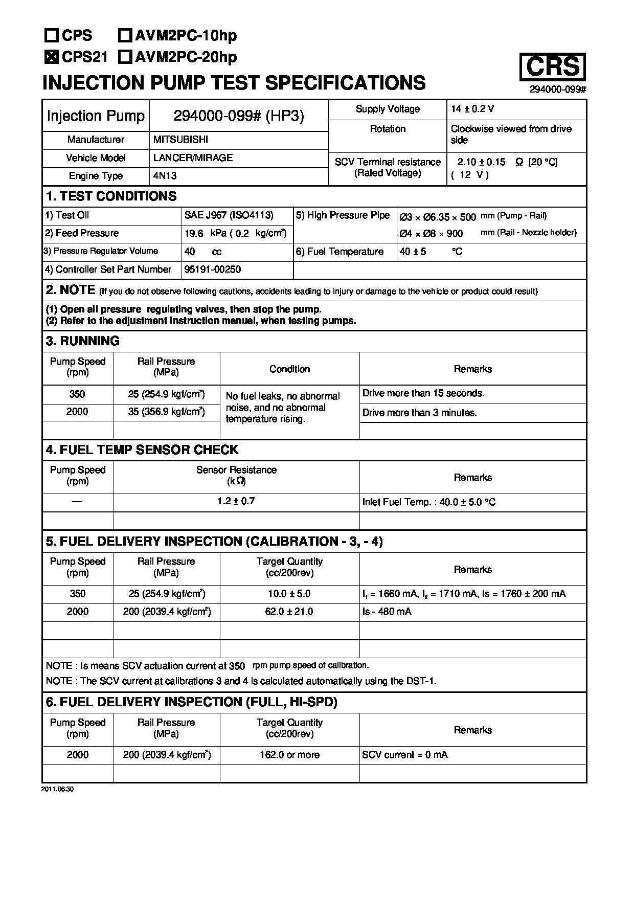
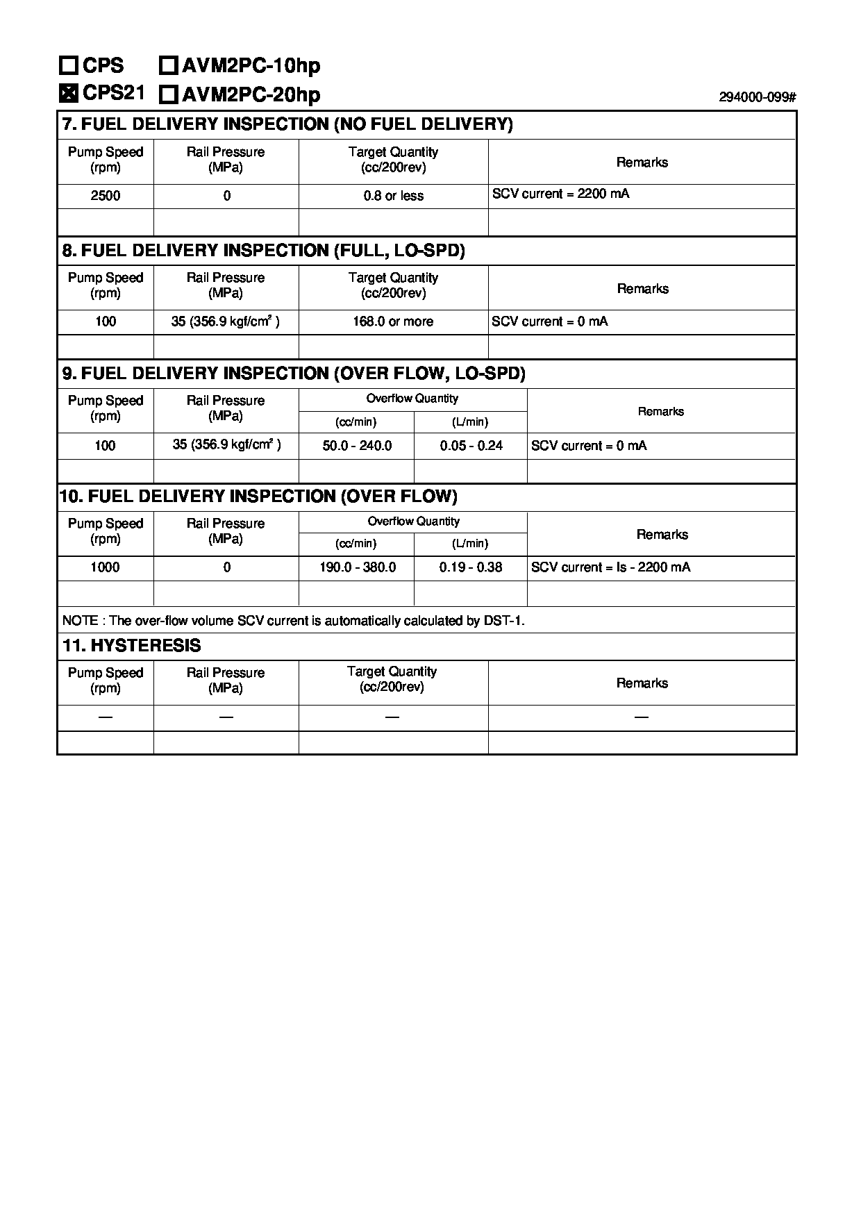
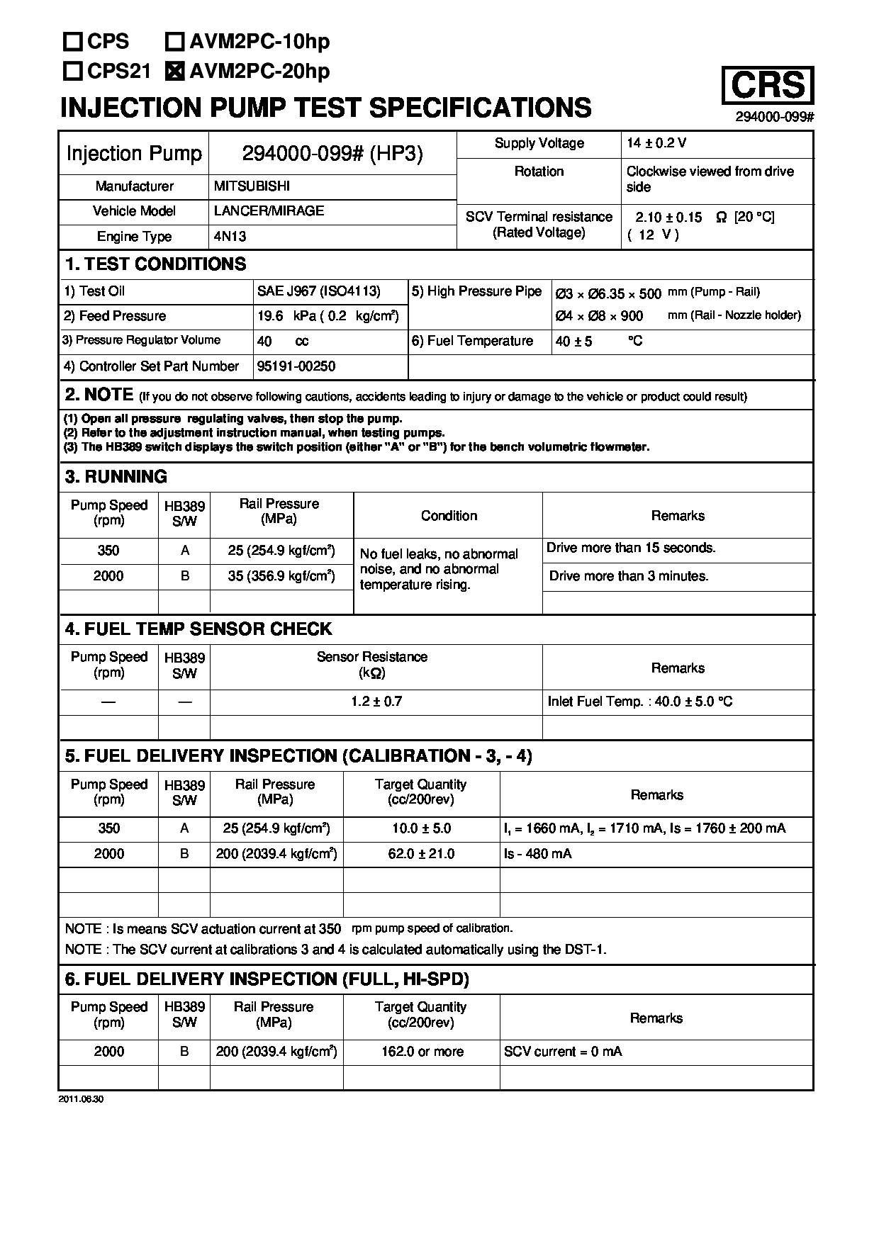
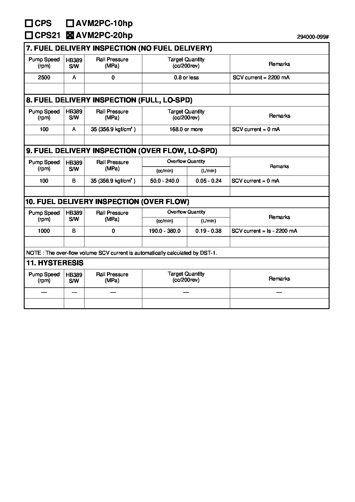
Test Calibration Data:
01EN099000
1460A043
01EN099000
1460A043
01EN099000
1460A043
02EN099000
1460A043
02EN099000
1460A043
02EN099000
1460A043
2940000990
1460A043


Information:
1. Disconnect the fuel ratio control sensing line (1). Remove the sensing line clamp bolt (2).2. Disconnect the air compressor water return line (6). 3. Remove the cylinder head air inlet line (3).4. Remove the retaining bolts (4) and the fan drive mounting bracket (5).5. Remove the cylinder head retaining bolts. Attach a hoist and remove the cylinder head assembly - weight 164 lbs. (74,4 kg).Install Cylinder Head
1. Thoroughly clean the sealing surfaces of the cylinder head and cylinder block. Position a new head gasket on the engine and install the cylinder head.2. Install the push rods and rocker shaft assembly.3. Coat the threads of the cylinder head retaining bolts with 4S9416 Anti-Seize Compound. Install bolts and washers, and tighten them in the following sequence: 1 - Tighten all numbered bolts in numerical order to 115 lb. ft. (15,9 mkg).2 - Retighten all numbered bolts in numerical order to 175 5 lb. ft. (24,2 0,7 mkg).3 - Finally, retighten all numbered bolts (hand torque only) in numerical order to 175 5 lb. ft. (24,2 0,7 mkg).4 - Tighten all lettered bolts in alphabetical order to 22 lb. ft. (3,0 mkg).5 - Retighten all lettered bolts in alphabetical order to 32 5 lb. ft. (4,4 0,7 mkg).6 - Finally, retighten all lettered bolts (hand torque only) in alphabetical order to 32 5 lb. ft. (4,4 0,7 mkg).4. Adjust the inlet and exhaust valve clearance as covered in INSTALL ROCKER SHAFT ASSEMBLY AND PUSH RODS.5. Connect the air compressor water return line.6. Connect the fuel ratio control sensing line and install the sensing line clamp bolt.7. Install the fan drive mounting bracket and retaining bolts.concluding steps: a) install water temperature regulatorb) install valve coverc) install precombustion chambersd) install exhaust manifold
1. Thoroughly clean the sealing surfaces of the cylinder head and cylinder block. Position a new head gasket on the engine and install the cylinder head.2. Install the push rods and rocker shaft assembly.3. Coat the threads of the cylinder head retaining bolts with 4S9416 Anti-Seize Compound. Install bolts and washers, and tighten them in the following sequence: 1 - Tighten all numbered bolts in numerical order to 115 lb. ft. (15,9 mkg).2 - Retighten all numbered bolts in numerical order to 175 5 lb. ft. (24,2 0,7 mkg).3 - Finally, retighten all numbered bolts (hand torque only) in numerical order to 175 5 lb. ft. (24,2 0,7 mkg).4 - Tighten all lettered bolts in alphabetical order to 22 lb. ft. (3,0 mkg).5 - Retighten all lettered bolts in alphabetical order to 32 5 lb. ft. (4,4 0,7 mkg).6 - Finally, retighten all lettered bolts (hand torque only) in alphabetical order to 32 5 lb. ft. (4,4 0,7 mkg).4. Adjust the inlet and exhaust valve clearance as covered in INSTALL ROCKER SHAFT ASSEMBLY AND PUSH RODS.5. Connect the air compressor water return line.6. Connect the fuel ratio control sensing line and install the sensing line clamp bolt.7. Install the fan drive mounting bracket and retaining bolts.concluding steps: a) install water temperature regulatorb) install valve coverc) install precombustion chambersd) install exhaust manifold