Rating:
Information pump assy supply Denso
Product
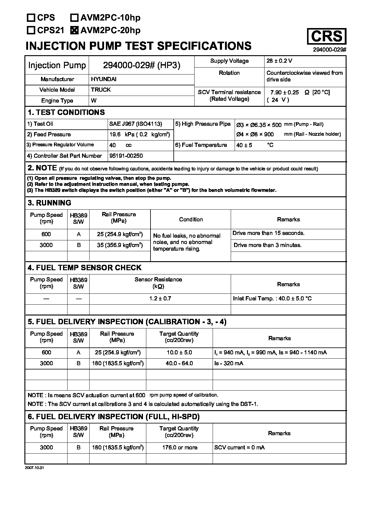
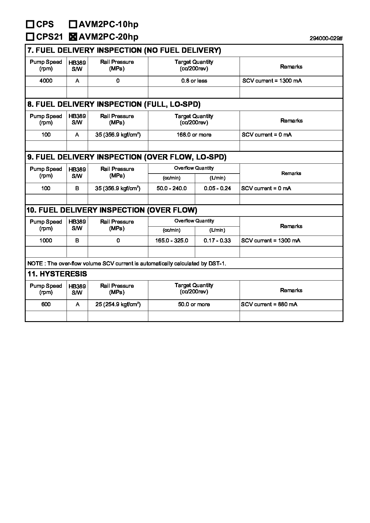
Fuel Injection Pump
Vehicle engine
TRUCK W
Engine
W
Serial start-end
0404-
Info
Injector Nozzle
Compare Prices: .
As an associate, we earn commssions on qualifying purchases through the links below

China Made Common Rail Scv Valve 294009-1221 2940091221 Fuel Pump Suction Control Valve For HP3 Pump - (Style: A, Color: 294000-0290)
Generic Color: 294000-0290
Generic Color: 294000-0290
SCV Control Valve 294009-1221 294200-0270 294000-0290 294000-0294 is Used for HP3 Pump, Hino Isuzu, Xichai Shanghai - (Color: 294000-0290)
Generic Color: 294000-0290
Generic Color: 294000-0290
Cross reference number
Part num
Firm num
Firm
Name
2940000290
33100-45700
HYN
PUMP ASSY SUPPLY
2940000290
3310045700
HYN
PUMP ASSY, SUPPLY
Test Calibration Data:
02EN029100
33100-45700
02EN029100
33100-45700
Information:
Introduction
A new steel engine oil lines group is available for the engines that are listed above. The Engine Oil Lines Group is available for repair of the flexible high pressure oil line that is on the Hydraulic Electronic Unit Injector Pump. The engine oil lines group is adaptable to the serial numbers that are listed above. The engine oil lines group is effective with the following serial numbers: 5GG6100-UP, BEJ6915-UP and 3GS2119-UP.
Table 1
Required Tools
Tool Part Number Description
A 180-0186 Removal Tool
Table 2
Components in Engine Oil Lines Group
Callout Part Number Description Quantity
16 247-3755 Tube As 1
17 6V-8636 Connector 1
18 221-3494 O-Ring Seal 2
19 214-7568 O-Ring Seal 2
20 6V-8724 Elbow 1 Removal of the Flexible Oil Line
Keep all parts clean from contaminants.Contaminants may cause rapid wear and shortened component life.
Care must be taken to ensure that fluids are contained during performance of inspection, maintenance, testing, adjusting and repair of the product. Be prepared to collect the fluid with suitable containers before opening any compartment or disassembling any component containing fluids.Refer to Special Publication, NENG2500, "Caterpillar Dealer Service Tool Catalog" for tools and supplies suitable to collect and contain fluids on Caterpillar products.Dispose of all fluids according to local regulations and mandates.
Illustration 1 g01068766
Inlet fuel line (fuel transfer pump to cylinder head) (1) Connector (2) Hose assembly (3) Fuel transfer pump
Remove connector (1) and hose assembly (2) from the fuel transfer pump (3). Refer to Illustration 1. Retain these parts for the reinstallation.
Illustration 2 g01068729
Outlet fuel line (fuel transfer pump to secondary fuel filter) (4) Adapter (5) Tee (6) Elbow (7) Hose assembly
Remove adapter (4), tee (5), elbow (6), and hose assembly (7) from the fuel transfer pump (3). Refer to Illustration 2. Retain these parts for the reinstallation.Note: Modifications to the tools may need to be made in order to reduce interference with engine components. Refer to Illustration 3.
Illustration 3 g01007381
Modified 2P-5494 crowfoot wrench
Illustration 4 g01068745
(3) Fuel transfer pump (8) Bolt (9) Bolt (10) Washer (11) Adapter (15) HEUI pump (21) Clip
Remove the bolt (8) and the clip (21) from the top of the fuel transfer pump. Refer to Illustration 4.
Remove the bolt (9) and the washer (10) from the bottom of the fuel transfer pump (3). Refer to Illustration 4.
Remove fuel transfer pump (3). Refer to Illustration 4.
Illustration 5 g01068776
(12) 45 ° adapter (13) Hose assembly (14) Straight connector (15) HEUI pump
Remove hose assembly (13) from 45 degree adapter (12) and straight connector (14) by using removal tool (A). Refer to Illustration 5.
Remove 45 degree adapter (12) from the HEUI pump (15). Remove straight adapter (14) from the cylinder head. Discard the parts. Refer to Illustration 5.Installation of the Engine Oil Lines Group
Illustration 6 g01068779
(16) 247-3755 Tube As