Rating:
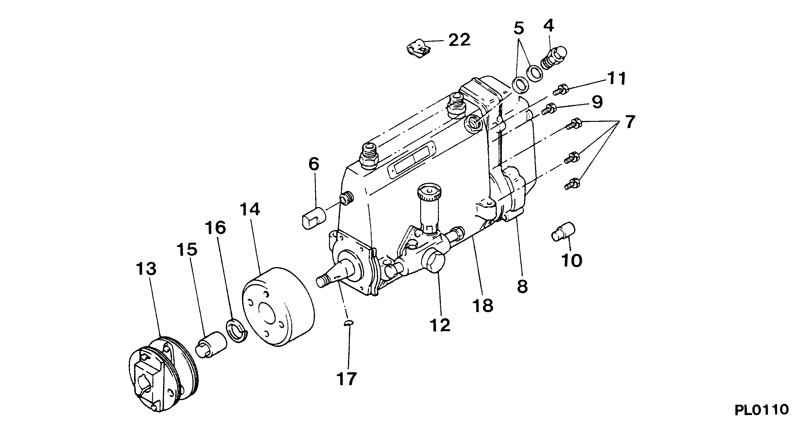
Information pump assy, injecti Denso
Components :
Scheme #.#:
№
Qty
Part num
Name
Remarks
Manufacture num
000
[01]
19100-09151
PUMP ASSY, INJECTI
A6,R801
22010-6621
HINO
Include in ##:
19100-09151
as PUMP ASSY, INJECTI
Cross reference number
Part num
Firm num
Firm
Name
19100-09151
22010-6621
PUMP ASSY, INJECTI
Information:
Removal of Rocker Shaft Assembly
(1) Loosen the adjusting screws on the rockers by rotating each screw about one turn.(2) Loosen the short bolts on the rocker shaft brackets first, then loosen the long bolts to remove the rocker shaft assembly from the cylinder head.
Incorrect bolt loosening sequence can result in the damage to the rocker shaft brackets.
(3) Remove the pushrods.
Removal of rocker shaft assemblyDisassembly of Rocker Shaft Assembly
Arrange the disassembled rockers in the order of removal, so that the rockers can be reinstalled exactly in the opposite sequence.This ensures the same rocker shaft clearances as before.
Disassembly of rocker shaft assemblyRemoval of Cylinder Head Bolts
Remove the cylinder head bolts from the cylinder head, and lift the cylinder head vertically to detach it from the crankcase. If there is any problem in the cylinder head, before removing the bolts, examine the cylinder head bolt tightening condition by checking the bolt tightening torque with a torque wrench.
Removal of cylinder head boltRemoval of Valves and Valve Springs
Using the valve spring pusher, compress the valve spring squarely, then remove the valve cotter. If the valves are to be reused, mark them to indicate their original installation positions.
Removal of valve and valve springRemoval of Valve Stem Seals
To remove stem seals, pull with pliers. Do not reuse the removed stem seals.
Removal of valve stem sealCleaning of Cylinder Head Bottom Surface
Remove adhered gasket pieces from the bottom surface of the cylinder head, making sure not to scratch the surface. Use a scraper to remove large pieces first, then remove remaining small pieces by using an oilstone dampened with engine oil.
Cleaning of cylinder head bottom surfaceMeasurement of Piston Protrusions
Determine the amount of the protrusion of the piston. If the amount of piston protrusion does not conform to the standard, be sure to inspect and repair each bearing.(1) Determine the top dead center of the piston with a dial gage.(2) Attach a dial gage on the top surface of the crankcase, and set the indicator to zero (0).(3) Check the piston protrusion at three locations on the top surface of the piston, and obtain the average value. Subtract the amount of piston protrusion from the compressed thickness of the gasket to determine the clearance between the piston top and cylinder head.
Piston protrusions must comply with the standard to ensure proper engine performance and prevent the interference between the valves and pistons.
Measurement of piston protrusionFlywheel
Removal of Flywheel
(1) To prevent the flywheel from rotating, have someone hold the crankshaft pulley with a wrench.(2) Remove one of the flywheel mounting bolts.
The person holding the flywheel in place should exercise utmost caution, and communicate with the person removing the flywheel during the removal process to ensure safety.
(3) Screw a safety bar (M12x1.25mm) in the threaded hole from which the bolt was removed in the above step, then remove the remaining bolts.(4) Hold the flywheel securely with both hands, jiggle it back and forth, and pull it straight out.
When removing the flywheel, be careful not to cut your hands with the ring gear.
Removal