Rating:
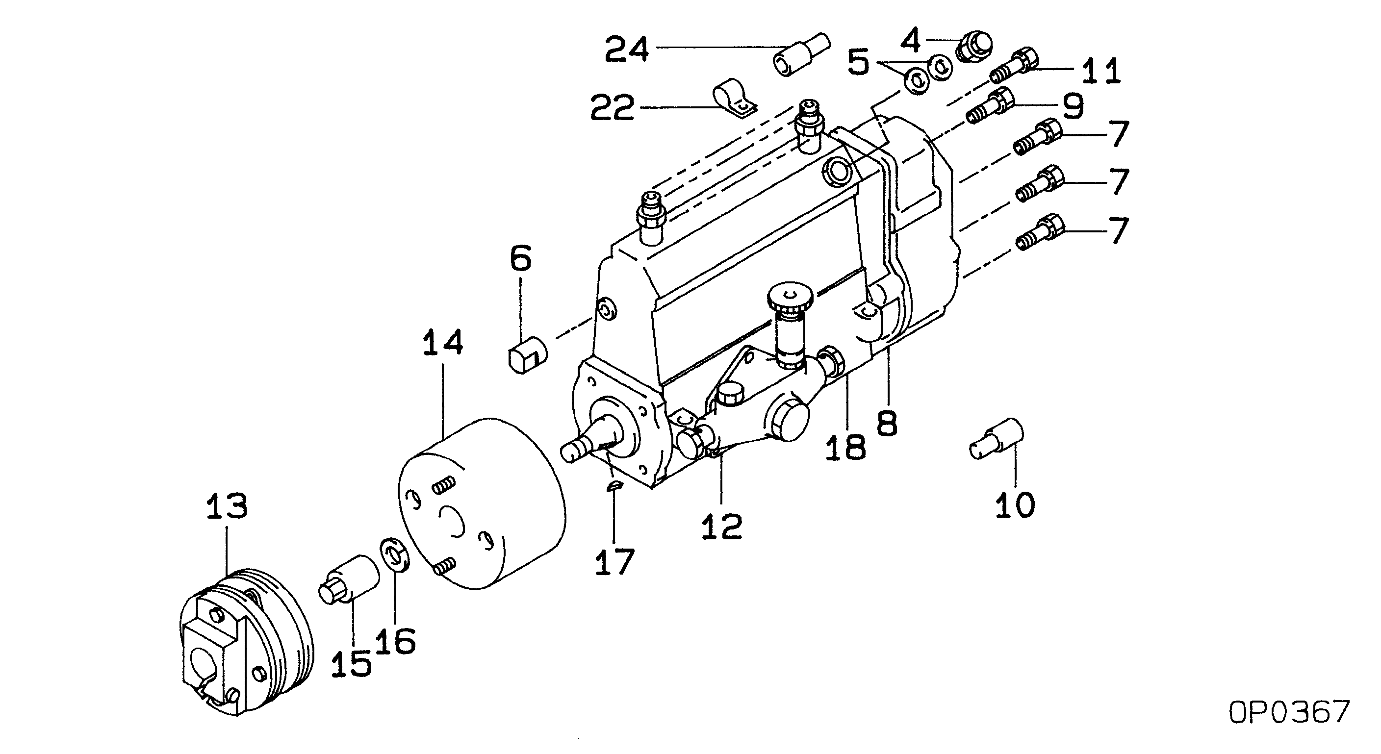
Information pump assy, injecti Denso
Components :
Scheme #.#:
№
Qty
Part num
Name
Remarks
Manufacture num
000
[01]
19100-07431
PUMP ASSY, INJECTI
A6,R801
22010-5841
HINO
Include in ##:
19100-07431
as PUMP ASSY, INJECTI
Cross reference number
Part num
Firm num
Firm
Name
19100-07431
22010-5841
PUMP ASSY, INJECTI
Information:
General Information
All of the Series 300 OEM Engines are valve-in head, vertical in-line, diesel engines.Engine Lubrication System
Fig. 1-Oil Pressure Regulating ValveThe components of the lubrication system consist of an oil pump, oil filter, oil pressure, control valve, and an oil cooler, if equipped. The location of these components varies with engine model as shown in (1, 3, Fig. 1) for the oil pressure control valves and (2, 4, Fig. 1) for the oil coolers.As the system operates, the oil is pumped through the oil cooler (if equipped) and cooled by the engine coolant. The oil is then passed through the oil filter. After filtering, the oil is distributed to various areas of the engine to provide both cooling and lubrication.The oil pressure control valve (locations shown in Fig. 1) is used to maintain and regulate engine oil pressure. IMPORTANT: The oil filter is equipped with an oil pressure relief valve that allows the oil to pass if the filter would become plugged. Replace it only with a JOHN DEERE filter.Engine Cooling System
Fig. 2-Cooling SystemThe cooling system for the power unit consists of a radiator (1, Fig. 2), water pump (4), one or two thermostats located in the same area (2), and a water manifold located as shown (3) on some engines.The pump draws coolant from the bottom of the radiator and discharges it into the main coolant gallery on the right-hand side of the engine. Coolant from the gallery circulates through the block to cool block and cylinder liners, then flows into the cylinder head. From the cylinder head, the coolant passes into the water manifold and thermostat housing.
Fig. 3-Engine ThermostatIf the thermostat(s) Fig. 3 are closed (as during warm-up periods), coolant is directed back to the pump to be recirculated. This provides a faster and more uniform warm-up.The radiator is equipped with a 7 psi (0.5 bar) (0.5 kg/cm2) pressure cap which acts as a relief valve and keeps pressure within the system at 6.25 to 7.50 psi (0.4 to 0.5 bar) (0.4 to 0.5 kg/cm2) level. Pressurizing the system reduces the loss of coolant by evaporation, surging, or boiling. The efficiency of the system is therefore dependent on good seals at the radiator cap, hoses, and hose connections. All leaks, regardless of size, must be repaired quickly. A small drip can quickly become a stream under pressure.Fuel System
Fig. 4-Fuel SystemThe components of the fuel system consists of a fuel transfer pump (2, Fig. 4), fuel filter(s) (1), fuel injection pump (4), injection nozzles (3) and assorted fuel line between components.The fuel transfer pump delivers fuel from the tank to the filters.The filters remove impurities from the fuel.The injection pump pressurizes the fuel and sends it through the high pressure lines to the injection nozzles.Air Intake System
The components of the air intake system are the air cleaner and the intake manifold.Air enters the air cleaner. The air cleaner element removes impurities from the surrounding air.On diesel engines the air then enters the intake manifold which delivers it