Rating:
Information pump assy, injecti Denso
Components :
Scheme #.#:
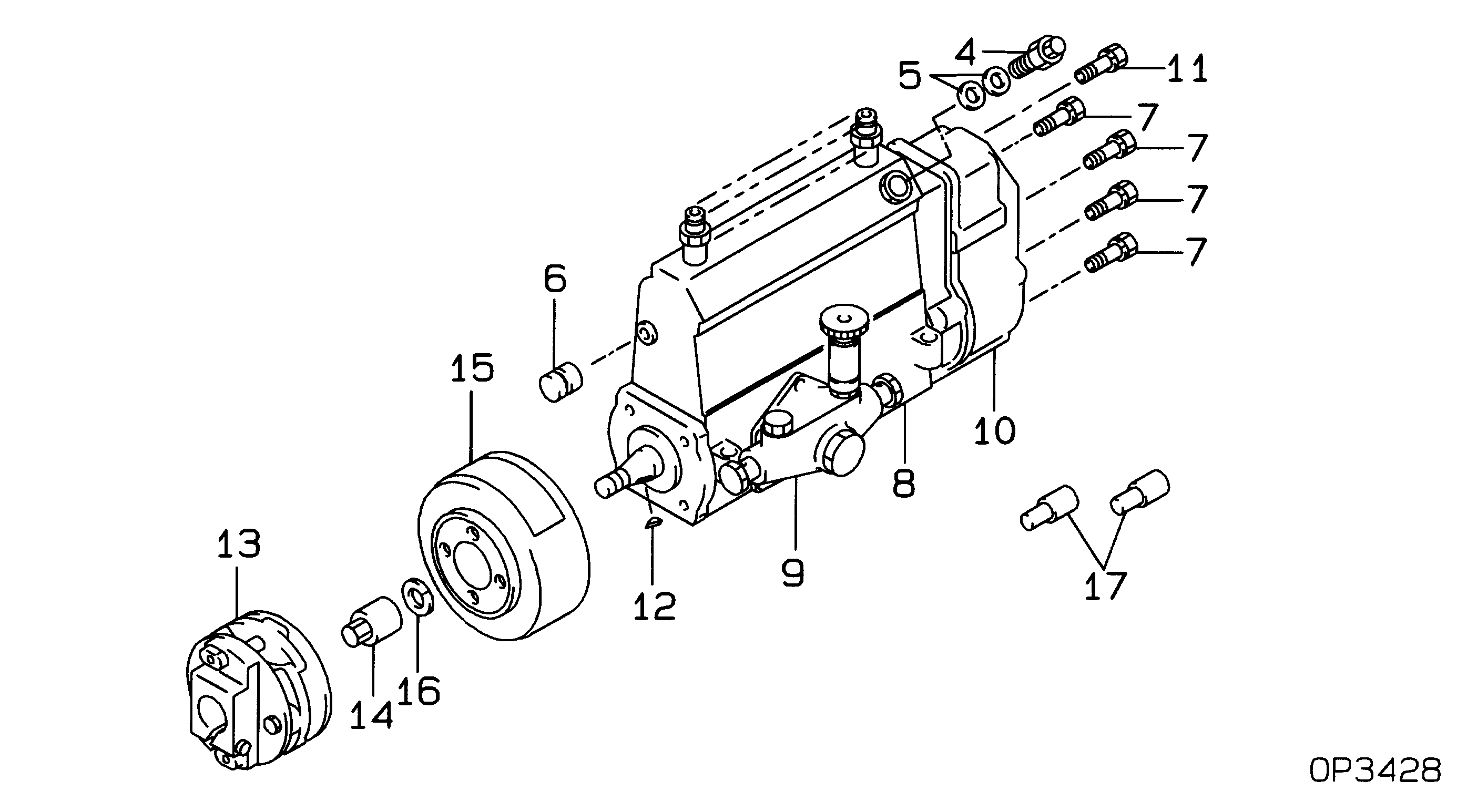
№
Qty
Part num
Name
Remarks
Manufacture num
000
[01]
19100-05791
PUMP ASSY, INJECTI
A6,R812
22010-5451
HINO
Include in ##:
19100-05791
as PUMP ASSY, INJECTI
Cross reference number
Part num
Firm num
Firm
Name
19100-05791
22010-5451
PUMP ASSY, INJECTI
Information:
1-1The serial No. is stamped both on the maker's nameplate (Fig. 1-1) and the crankcase.
1-3Engines of the F3/4/5/6L type have the serial number stamped at the back of the oil filler neck, on the flange for mounting the housing of the fuel injection pump.Fig. 1-3Maker's Nameplate
In addition to the engine serial No., the plate indicates the particular engine model and version respectively. Typical example BF6L 913 C:B = Engine with turbochargerF = Automotive or industrial engine6 = Number of cylindersL = Air-cooled9 = Number of series13 = Stroke of piston in cmThe suffix letters of the engine model designation mean:C = With charge air coolerG = Engine for fork-lift truckT = Mildly turbochargedW = Two-stage combustion system (swirl chamber)Further data of the nameplate:Rated power in kW (HP) and speed in rev/min. Letter "A" denotes continuous power (with overload capacity), both according to DIN 6270.De-rated industrial engines have an additional rating plate.The rating for automotive engines refers to DIN 70020.General Notes On Repair
To be successful, every repair job calls for precision workmanship, in clean and neat surroundings.
1-5The "front end" of the engine is understood to be the end opposite the flywheel, and the other engine faces are designated accordingly. Thus: Cylinder No. 1 is at the rear end = at the flywheel end. The cylinder numbers are applied to the crankcase, below the cylinder seating area. The sense of rotation of the engine is anti-clockwise, when facing the flywheel.Fig. 1-5
1-6The parts of the crankshaft assembly, timing gear, cylinders, pistons and cylinder heads should be numbered in sequence, unless they are already marked. The numbering should commence at the flywheel end.Fig. 1-6As the parts are dismantled, place them where they will not get damaged. Components that are subject to wear should be kept apart and should be gauged individually. If the low tolerances are exceeded, the components have to be replaced or rectified. In any case, fit new gaskets, packings and O-seals.The numbers of spare parts should be taken from the part number catalogue for the respective engine type. A good repair job that is to ensure satisfactory engine performance essentially calls for the use of genuine DEUTZ spare parts.Should bearing or pistons be damaged, the crankshaft and connecting rods should be inspected for cracks, if possible by the Magnaflux testing method. It is very important that the cause of the damage is established. Testing, repairs and/or reworking can be undertaken by the manufacturers or their appointed repair shops.
1-8For the repair work to be carried out on the removed engine, mounting on a swivelling assembly stand, special fixture No. 6067, is recommended.Fig. 1-8Tightening Instructions For Bolts And Studs
All bolts and studs tabulated shall first be hand-tightened to approx 30 Nm and then locked down alternately in stages until the specified angle degrees are obtained. Before assembling the bolts and studs, wet the threads and the bearing faces of the heads with motor oil. 1. Preloading
1-9Hold wrench so the thumb touches the end.Fig. 1-9Use a torque wrench for torques above 30