Rating:
Information pump assy, injecti Denso
Product
Fuel Injection Pump
Vehicle engine
INDUSTRIAL 6D125
Engine
6D125
Serial start-end
8706-
Info
Injector Nozzle
093500-2710
Injector nozzle:
0935002710
KIT List:
Part name
Kit1
Kit2
Components :
Scheme #.#:
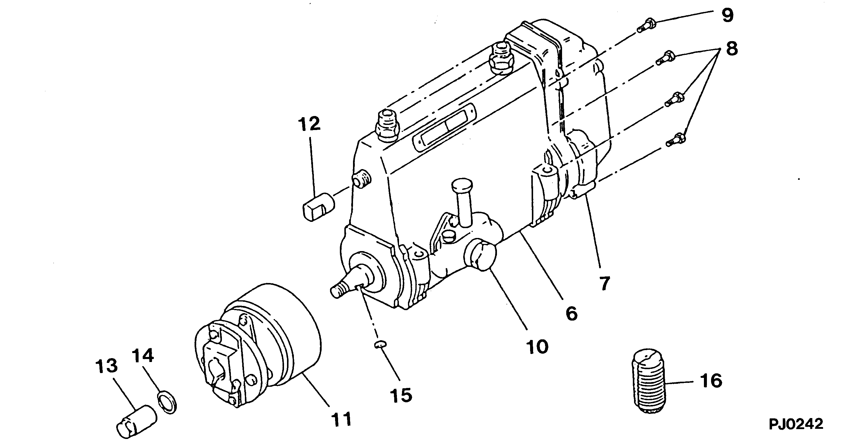
№
Qty
Part num
Name
Remarks
Manufacture num
000
[01]
19100-05230
PUMP ASSY, INJECTI
A6,RSV
-8810
Include in ##:
19100-05230
as PUMP ASSY, INJECTI
Cross reference number
Part num
Firm num
Firm
Name
19100-05230
PUMP ASSY, INJECTI
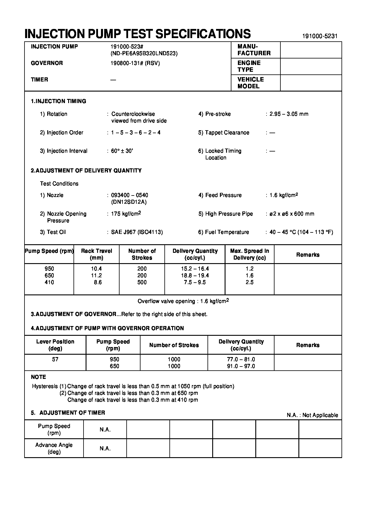

Information:
Table 1
Item 3408C / 3412C 3176B 3176C / 3196
Connector P14 P1 P1
(-) Battery Pin-21 Pin-5 Pin-5
(+) 8 VDC Pin-10 Pin-35 Pin-35
Cat Data (+) Pin-9 Pin-9 Pin-9
Cat Data (-) Pin-19 Pin-3 Pin-3
Illustration 1 g06449052
(A) Port ECM
(B) Cat Link Booster
(C) EVIM
(D) STBD ECM
(E) CAT Link Booster
(F) Engine Vision Display
Illustration 2 g06449056
(G) Connector A
(H) Connector B
Turn the power OFF to the engine ECM and display unit.
Remove the ECM connector-battery pin and reinsert it into pin-3 on the 4-pin DT connector B (2).
Remove the ECM connector +8 VDC pin and reinsert into pin-4 on the 4-pin DT connector B (2).
Remove the ECM connector (CAT Data+) pin and reinsert into pin-1 on the 4-pin DT connector B (2).
Remove the ECM connector (Cat Data-) pin and reinsert into pin-2 on the 4-pin DT connector B (2).
Insert the BLACK wire into the ECM connector-battery pin.
Insert the PINK wire into the ECM connector CAT Data+ pin.
Insert the WHITE wire into the ECM connector CAT Data- pin.
Insert the RED wire into the ECM connector +8 VDC supply pin.
Plug connector B (2) into connector A (1).
Apply power to the ECM.