Rating:
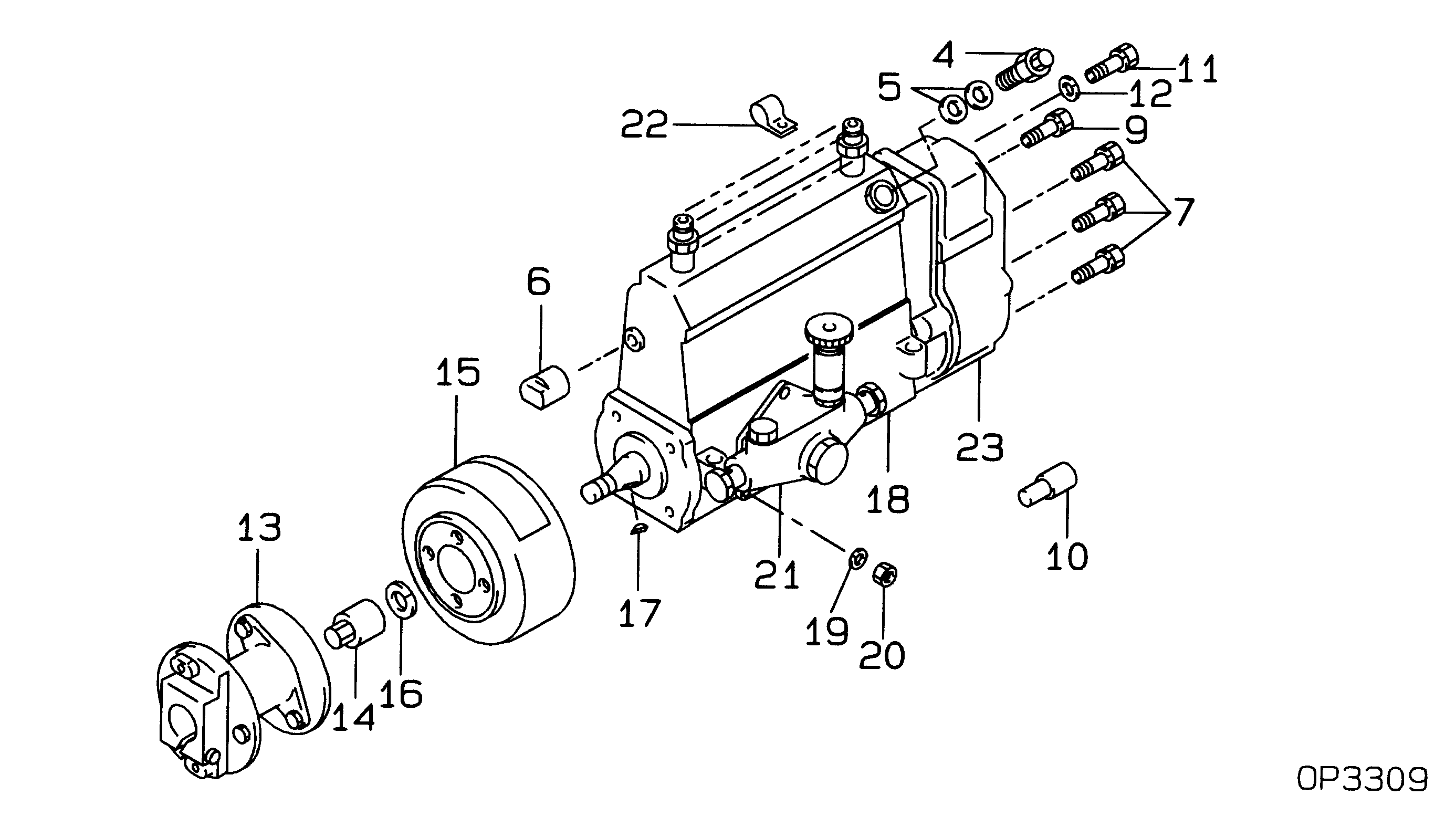
Information pump assy, injecti Denso
Components :
Scheme #.#:
№
Qty
Part num
Name
Remarks
Manufacture num
000
[01]
19000-08073
PUMP ASSY, INJECTI
A6,R801
22010-3782
HINO
Include in ##:
19000-08073
as PUMP ASSY, INJECTI
Cross reference number
Part num
Firm num
Firm
Name
19000-08073
22010-3782
PUMP ASSY, INJECTI
Information:
Operate the controls ONLY with the engine running. Report any needed repairs noted during operation.
Engine and Marine Transmission Operation
Operate a cool engine at low load. After normal oil pressure is reached and the temperature gauges begin to move, the engine may be operated at full load.Transmission Selector Lever
Typical ExampleFull power is transferred from the engine through the marine transmission, in either forward (1) or reverse (3) rotation, to the propeller shaft. The engine transmissions can be operated by mechanical, hydraulic, pneumatic or electrically actuated controls for the forward and reverse drives.A control valve directs the flow of oil to either the forward or reverse clutch (for forward or reverse operation). The valve is operated by a selector lever, which can be remotely operated (from the pilot station) or operated manually from the transmission (in the engine room).Moving and Getting Underway
The marine transmission selector valve is usually operated from the pilot house. It can also be operated at the marine transmission. Pilot house controls must be adjusted so as to permit full travel of the selector lever on the marine transmission, and full engagement of the clutch plates.To get underway after the engine has started and is warm:1. Fully engage the marine transmission control lever in the desired direction of travel. Allow one second before increasing engine speed.2. Wait a sufficient amount of time to allow complete engagement of the clutch.3. Gradually increase engine speed as required.Docking or Traveling (Direction Change)
The engine torque must be able to overcome the propeller and drive line inertia, the marine transmission inertia and the propeller slip stream torque. 1. Reduce engine speed to LOW IDLE.
Do not shift across NEUTRAL position without a few seconds delay. When reversing direction of travel (propeller rotation), stop at least two seconds in the position to allow the clutch plates to completely disengage, and the propeller to stop turning. A direct through-shift will cause severe shock loads to the engine, marine gear and hull. Also, it can cause the engine to reverse its rotation. If the engine reverses rotation, the engine and marine transmission oil pumps will be running opposite normal rotation. Oil will be pulled from the bearings and cause severe damage.
2. Move the marine transmission control lever to the NEUTRAL position.3. Move the marine transmission control lever to the engaged position. Wait a sufficient amount of time to allow complete engagement of the clutch before gradually increasing engine speed. The marine gear rotation should not be changed at full engine speed. To prevent the propeller from stalling or reversing the engine's rotation gradually increase engine speed as the clutch is engaged. A sequenced engine control system may be required. This equipment consists of a throttle boost with an optional shaft brake. The throttle boost system momentarily increases engine speed as the marine transmission selector lever is moved from NEUTRAL to the engaged position. The throttle boost is released upon completion of clutch engagement. The governor setting then regulates the engine speed.With the selector lever in the