Rating:
Information pump assy, injecti Denso
Product
Fuel Injection Pump
Vehicle engine
INDUSTRIAL EC100
Engine
EC100
Serial start-end
8403--8504
Info
Injector Nozzle
093500-0900
Injector nozzle:
0935000900
KIT List:
Part name
Kit1
Kit2
Components :
Scheme #.#:
№
Qty
Part num
Name
Remarks
Manufacture num
000
[01]
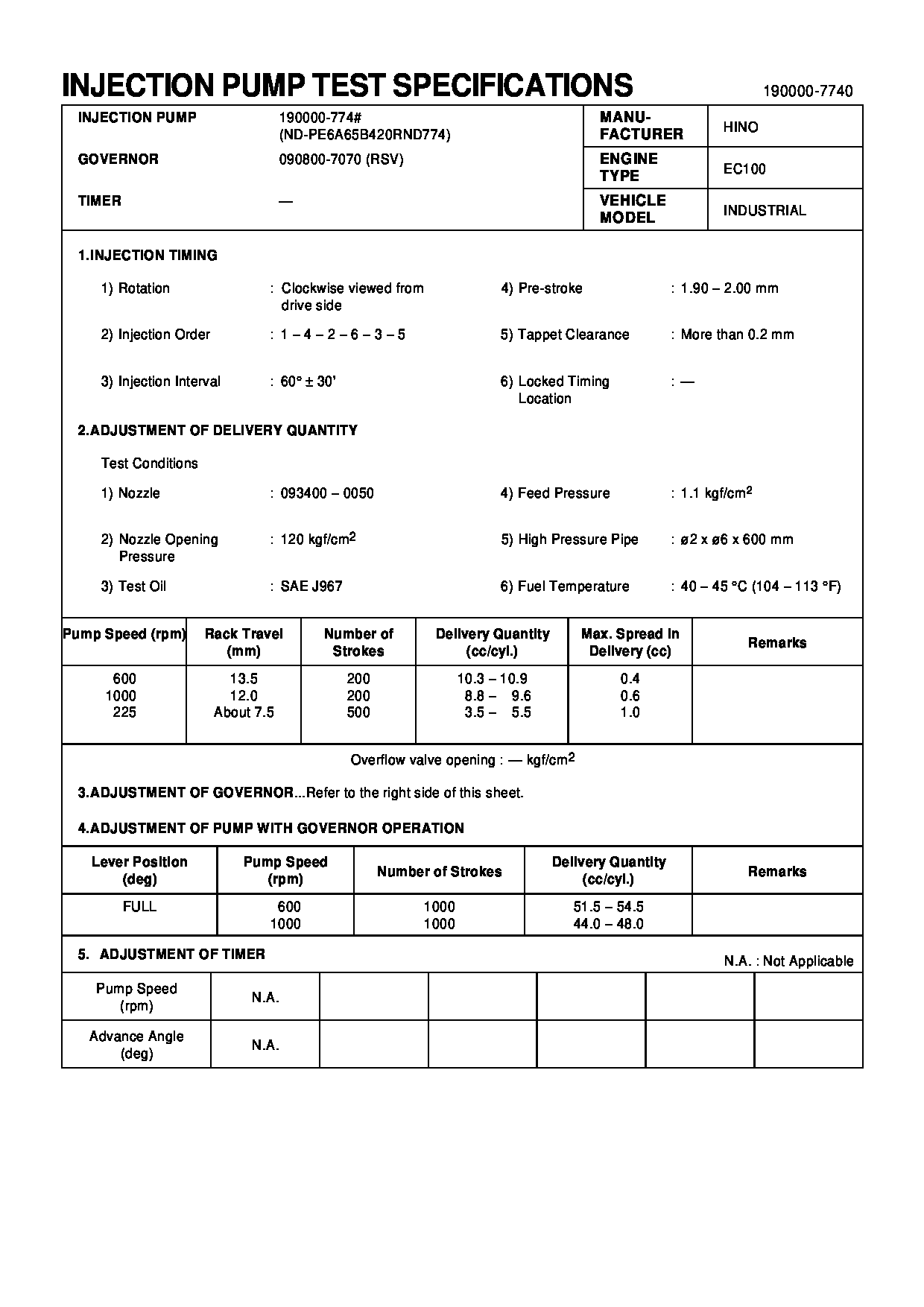
19000-07740
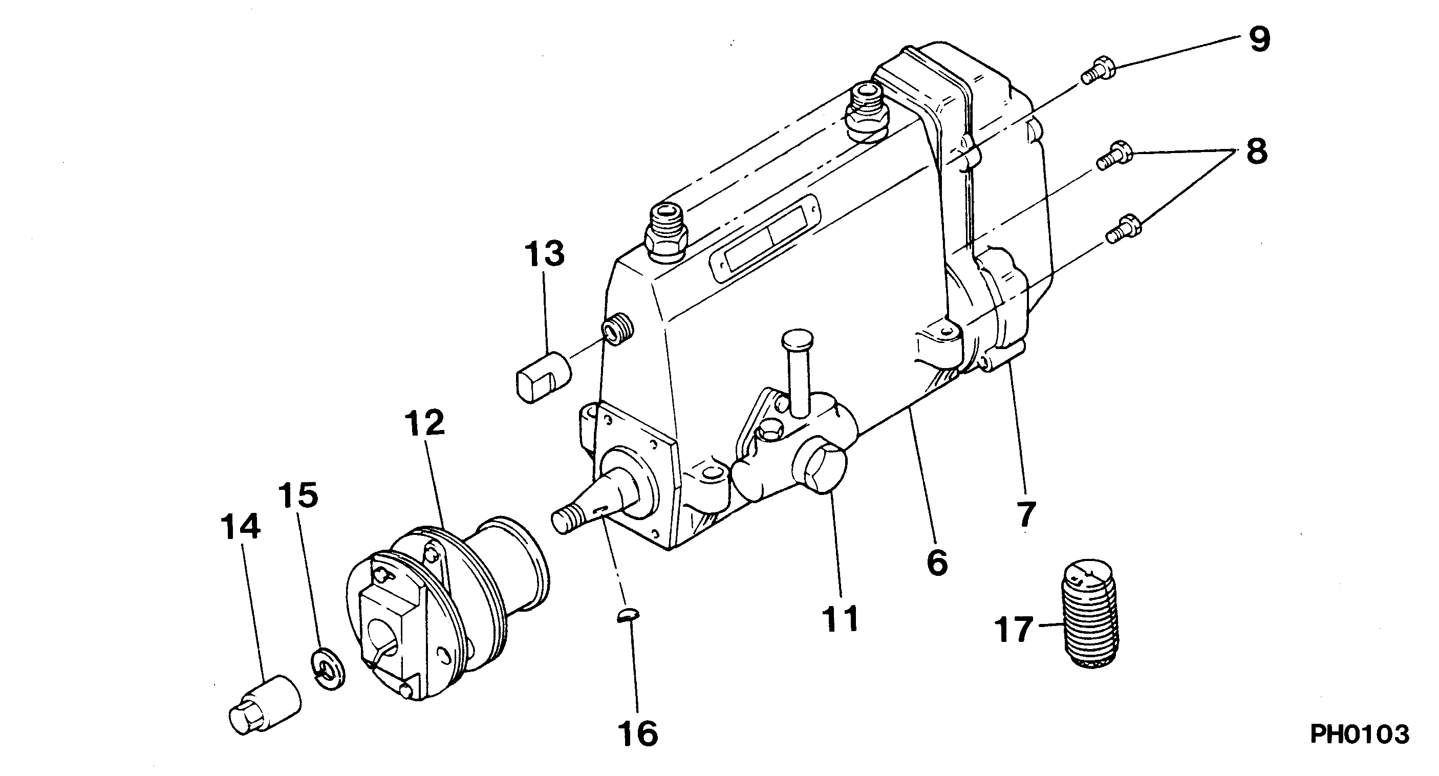
PUMP ASSY, INJECTI
A6,RSV
22030-1640
HINO
Include in ##:
19000-07740
as PUMP ASSY, INJECTI
Cross reference number
Part num
Firm num
Firm
Name
19000-07740
22030-1640
PUMP ASSY, INJECTI
1900007740
22030-1640
HINO
PUMP ASSY, INJECTI

Information:
Towing Information
If the vessel cannot continue under its own power, it is recommended that the vessel be towed. If pressurized oil cannot be supplied to the marine gear shaft bearings while being towed, the propeller shaft must be secured so as to prevent the turning shaft (caused by the propeller windmilling through the water) from damaging the marine gear shaft bearings.
Turning of the propeller shaft without proper lubrication for long periods will damage the marine gear shaft bearings.
After the shaft has been secured, have the towing vessel travel at slow speed in order to minimize the windmilling force on the propeller. If, while the vessel is being towed and the marine gear is allowed to windmill for long periods, the engine must be started and the marine gear operated for five minutes every twelve hours to lubricate the shaft bearings.There are several ways of preventing shaft rotation; the correct method depends upon the turning force of the propeller, and the construction of the propeller shaft tunnel. Use the method best suited for the type of installation.* On small vessels, wrap a heavy rope around the propeller shaft. The number of wraps needed will depend upon the mass of the propeller and propeller shaft.* Secure the rope in the opposite direction of shaft rotation.* Remove one or more bolts from the companion flange coupling. Bolt a chain to the companion flange. Wrap the chain several times around the propeller shaft.* Secure the loose end of the chain at a right angle to the shaft and in opposite direction of shaft rotation.* For vessels equipped with a shaft brake, the shaft brake may be applied if there is sufficient air pressure available.Come-Home Method
MG514C Marine Gear Only
If the marine transmission oil pressure is absent and the clutch can NOT be engaged, use the come-home method if there is no other means to return to port. The engine must be warm. If necessary, start and allow engine to idle until it is warm.
Use the come-home method ONLY in an emergency situation. If the marine transmission lubricating oil pressure is absent, travel with extreme care and at minimum engine speed to avoid damaging transmission shaft bearings.
1. Stop the engine.
Always shut off the fuel supply and disconnect starting system before performing any repair procedures. Accidental engine rotation or starting can cause personal injury.
2. Mechanically engage the "ahead" clutch in the following procedure.a. Remove two access plugs from the manifold for the forward or reverse clutch cylinder.b. Use a 9S9082 Engine Turning Tool to turn the engine flywheel and crankshaft to make an alignment of the lock-up setscrews with the plug openings.c. Alternately tighten the hex socket setscrews until they are tight.d. Again use the 9S9082 Engine Turning Tool to turn the engine flywheel to make an alignment of the two remaining setscrews and tighten them.e. Install the two access plugs in the manifold. The drive and driven clutch plates are now mechanically clamped together for a solid drive through the clutch. The transmission