Rating:
Information pump assy, injecti Denso
Components :
Scheme #.#:
№
Qty
Part num
Name
Remarks
Manufacture num
000
[01]
19000-07312
PUMP ASSY, INJECTI
A6,R721
22090-1080
HINO
000
[01]
19000-07312
PUMP ASSY, INJECTI
A6,R721
22090-1081
HINO
Include in ##:
19000-07312
as PUMP ASSY, INJECTI
19000-07312 PUMP ASSY, INJECTI
Cross reference number
Part num
Firm num
Firm
Name
19000-07312
22090-1080
PUMP ASSY, INJECTI
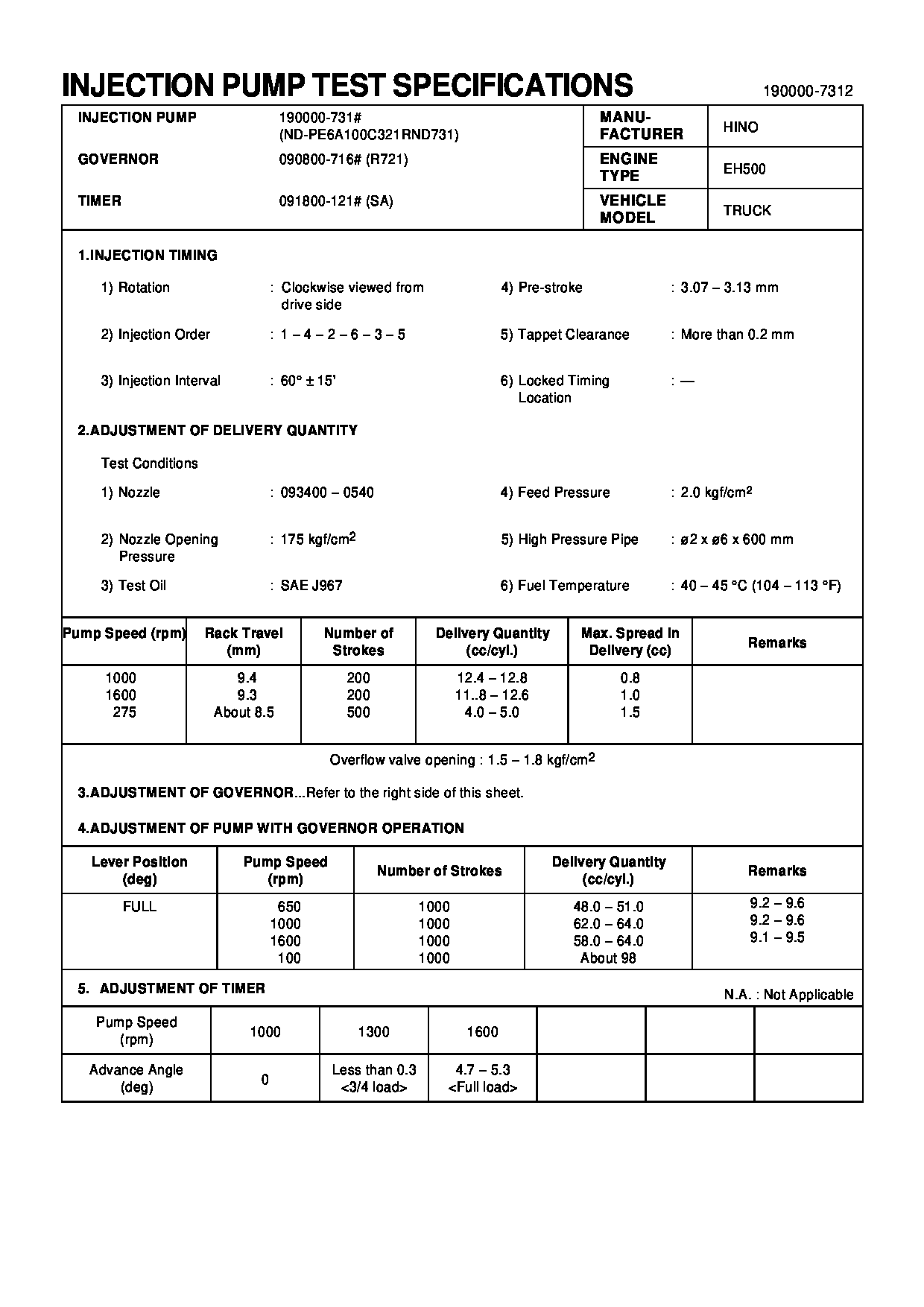
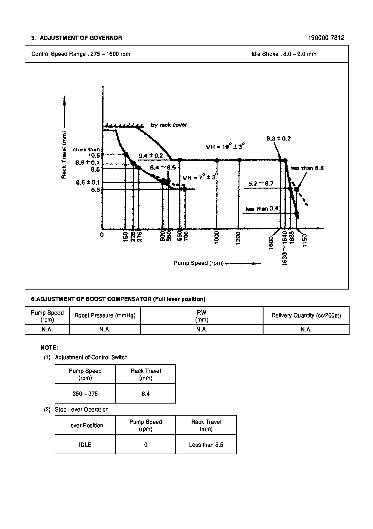
Test Calibration Data:
1900007310
22090-1080
1900007311
22090-1080
1900007312
22090-1080
Information:
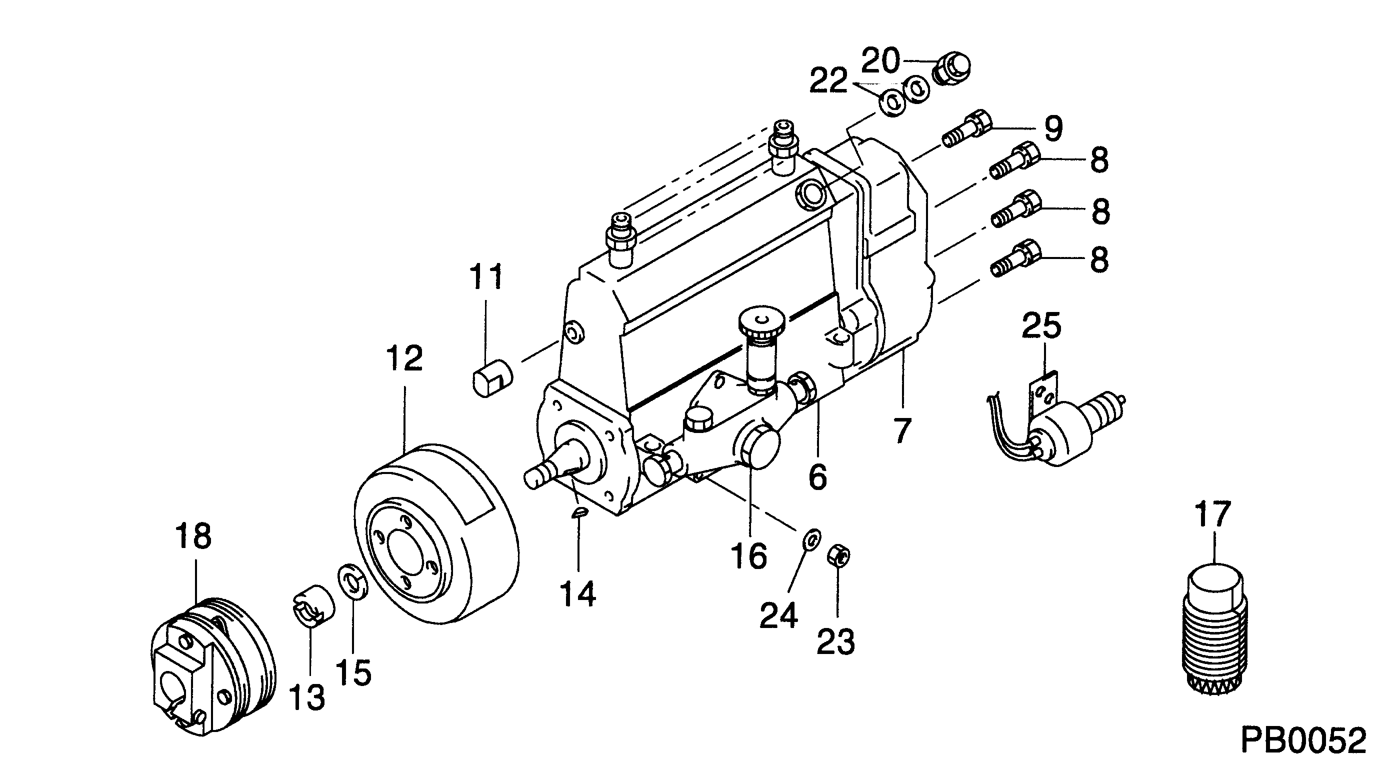
1. Disconnect solenoid lead wires (1) and (3) from the terminal in the Jacobs spacer.2. Remove eight Jacobs nuts (2) and four jacobs bolts that hold the Jacobs spacers to the valve cover bases. Remove Jacobs spacers (4). Do Steps 3 through 10 for each end of the engine. The front half of the engine is shown.3. Remove four Jacobs studs (5) and Jacobs washers. Remove three bolts (6) and remove valve cover base (7). 4. Remove Jacobs nut (8), Jacobs washers, Jacobs bolts (9), and the Jacobs washers that hold the Jacobs brake housing assembly in place.5. Remove Jacobs brake housing assembly (10). The Jacobs brake for the 3406B Truck Engine has only one support bracket (11).6. Remove Jacobs head bolts (12), and remove Jacobs support brackets (11) from the cylinder head. 7. Remove inner fuel lines (13). 8. Remove Jacobs washers (14) and Jacobs shims (15) from the Jacobs stud assemblies. 9. Remove bolt (17) and two Jacobs stud assemblies (16) that hold the rocker shaft assembly to the head. Remove rocker shaft assembly (18). 10. Remove Jacobs exhaust valve bridges (20) from the exhaust valves only. The intake valves have the Caterpillar intake valve bridges. Remove the Caterpillar intake valve bridges (19).Install Jacobs Engine Brake
Do each step for each end of the engine. The front half is shown.1. Put clean engine oil on the bridges and dowels.2. Install Jacobs exhaust valve bridges (20) and the Caterpillar intake valve bridges (19) on the dowels.3. Keep hand pressure on the bridges, and turn the adjustment screw clockwise until contact is made with the valve stem. Turn the screw an extra 20 ° to 30 °. This will make the dowel straight in the guide and compensate for gap (slack) in the threads. Hold the adjustment screw in this position, and tighten the locknut to a torque of 28 4 N m (21 3 lb.ft.). 4. Put rocker shaft assembly (18) in position on the cylinder head. 5. Install Jacobs washers (21) on the Jacobs stud assemblies (16). Put clean oil on the threads, and install washer and bolt (17) and Jacobs stud assemblies (16). Tighten the center bolt and Jacobs stud assemblies in increments of 70 N m (50 lb.ft.) each until a final torque of 450 N m (330 lb.ft.) is obtained.6. Make an adjustment to the valves to have a clearance of .015 (0.38 mm) for the intake valves and .030 (0.76 mm) for the exhaust valves. Tighten the locknuts to a torque of 28 4 N m (21 3 lb.ft.), and check the valve clearance again. See Testing And Adjusting for the correct procedure. 7. Install a new Jacobs O-ring seal (22) on the Jacobs oil supply adapter in the rocker shaft assembly. Put clean oil on the Jacobs O-ring seal.
Do not cause damage to the O-ring seals on the inner fuel lines.
8. Install inner fuel lines (13). Tighten the fuel line nuts to a torque of 40 7