Rating:
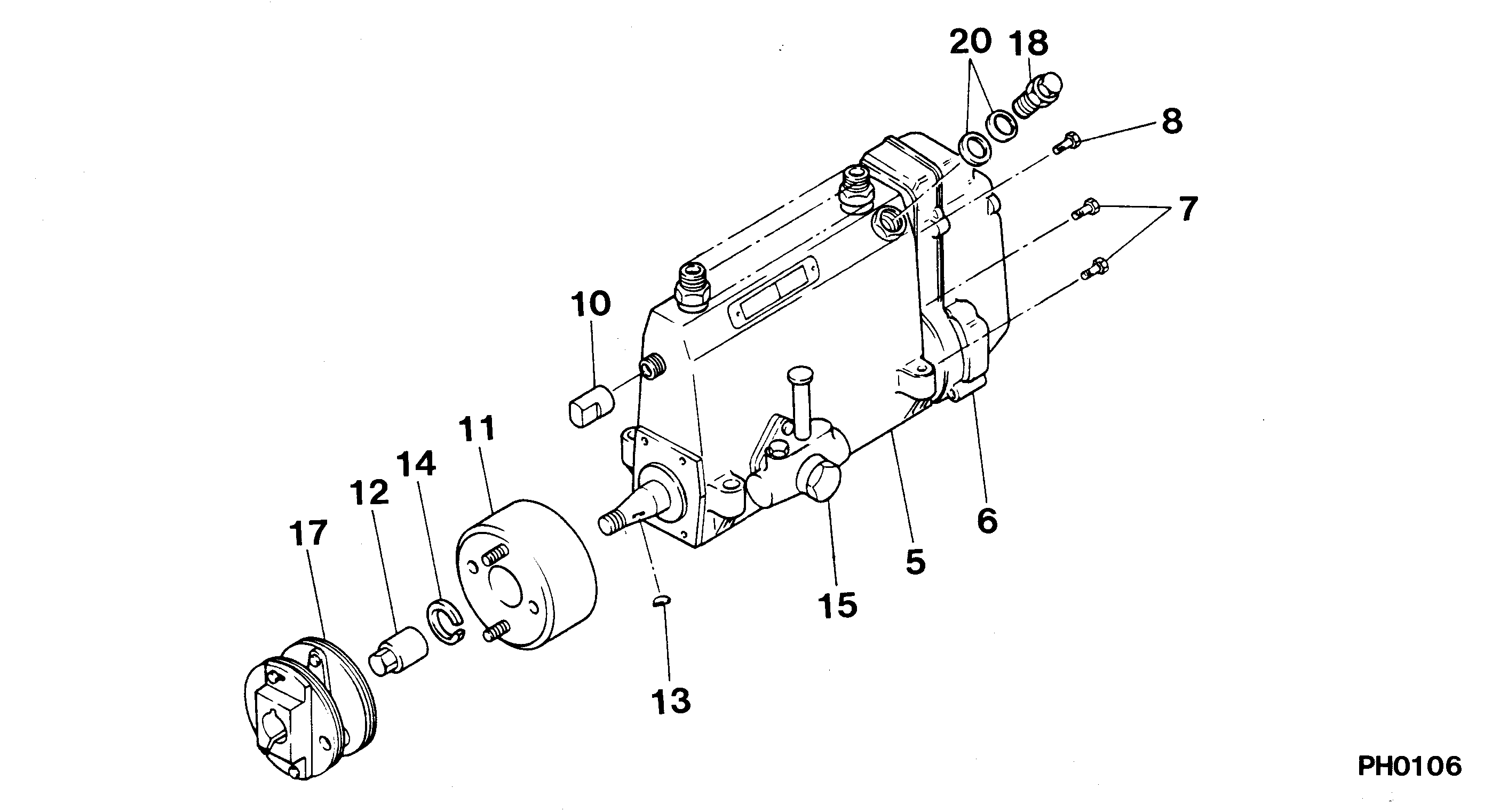
Information pump assy, injecti Denso
Components :
Scheme #.#:
№
Qty
Part num
Name
Remarks
Manufacture num
000
[01]
19000-02952
PUMP ASSY, INJECTI
A6,R722
22010-2113
HINO
Include in ##:
19000-02952
as PUMP ASSY, INJECTI
Cross reference number
Part num
Firm num
Firm
Name
19000-02952
22010-2113
PUMP ASSY, INJECTI
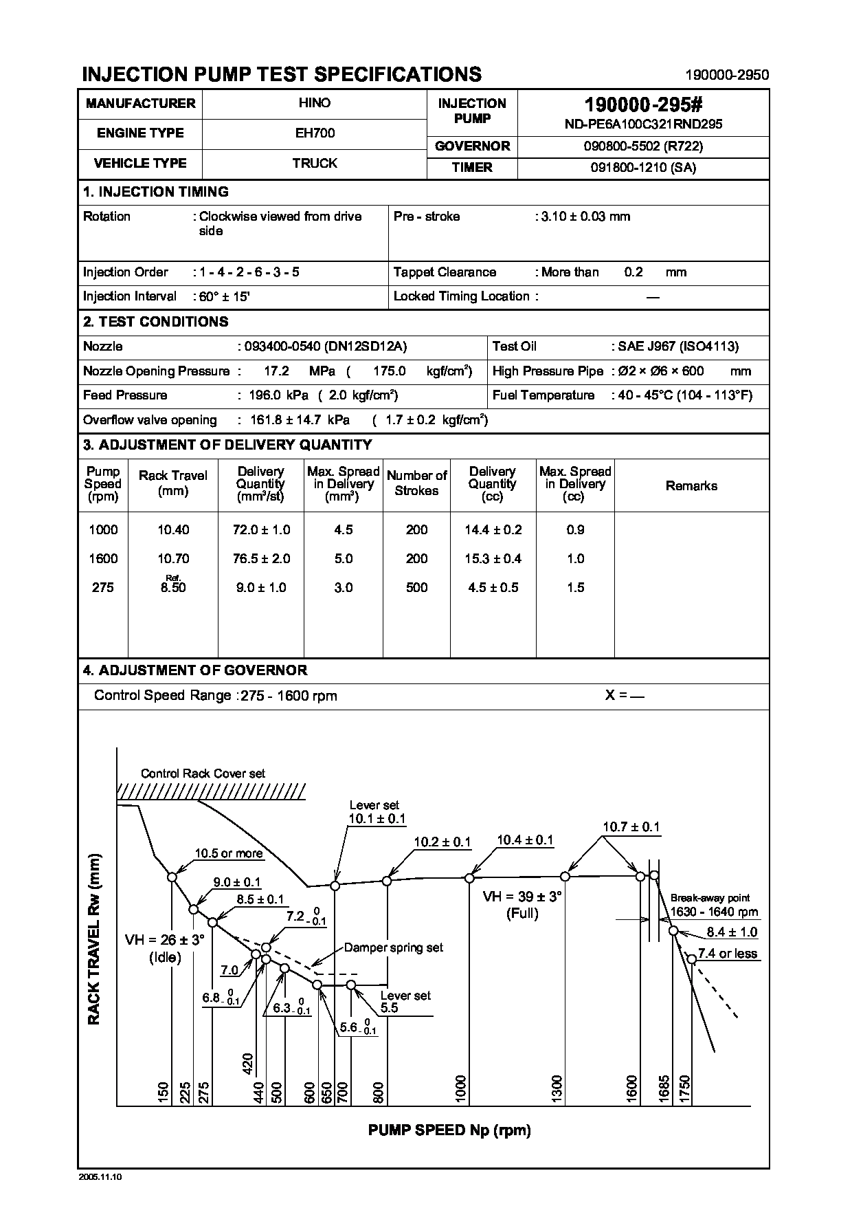
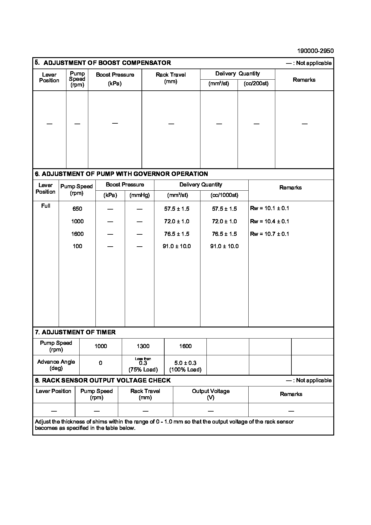
Test Calibration Data:
1900002950
22010-2113
1900002951
22010-2113
1900002952
22010-2113
1900002953
22010-2113
1900002954
22010-2113
Information:
START BY:a. remove vibration damper and pulley
The crankshaft front seal and wear sleeve come as a set and must be installed as a set. If a replacement of the seal is to be made, a replacement of the wear sleeve must also be made.
1. Make at least three holes in seal (1) with a hammer and a sharp punch. 2. Use tool (A) to remove seal (1). 3. Install tool (C) in the seal bore.4. Install tool (B) between tool (C) and wear sleeve (2). Turn tool (B) until the tool makes a dent (crease) in wear sleeve (2). Do this in three or more places until the wear sleeve is loose.5. Remove tools (B) and (C), and remove wear sleeve (2) from the crankshaft.Install Crankshaft Front Seal And Wear Sleeve
The crankshaft seal and wear sleeve come as a set and must not be separated from each other at any time. Carefully read Special Instruction, Form No. SMHS8508, that is included with each seal and wear sleeve before any handling of the seal group is made.
1. Install the front crankshaft seal and wear sleeve with tooling (A). Use the procedure which follows:a. Clean and make a preparation of the wear sleeve inside diameter and crankshaft outside diameter with 6V1541 Quick Cure Primer. Make an application of 9S3265 Retaining Compound to the crankshaft outside diameter before the wear sleeve is installed on the crankshaft. Do not let any Quick Cure Primer or Retaining Compound get on the lip of the seal.b. Install locator (1) and bolts (3) on the crankshaft.c. Seal (6) and wear sleeve (2) must be installed dry.
Make sure the seal is installed with the part number and the arrows showing crankshaft rotation toward the outside.
The front and rear seals and wear sleeves have different spiral grooves in the seal. Because of this type of design, the front seal group for an engine is different from the rear seal group. If a seal group is installed on the wrong end of the engine, oil can actually be taken out of the engine instead of moving the oil back into the engine.
d. Put wear sleeve (2) and seal (6) as a unit in position on locator (1).e. Put installer (4) in position on locator (1).f. Put clean engine oil on the face of nut (5) and its contact area on installer (4). Install nut (5) on locator (1).g. Tighten nut (5) until the inside surface of installer (4) comes in contact with locator (1).h. Remove tooling (A) from the crankshaft seal and wear sleeve. Tooling (A) will install the seal and wear sleeve to the correct depth on the crankshaft.END BY:a. install vibration damper and pulley