Rating:
Information pump assy, injecti Denso
Product
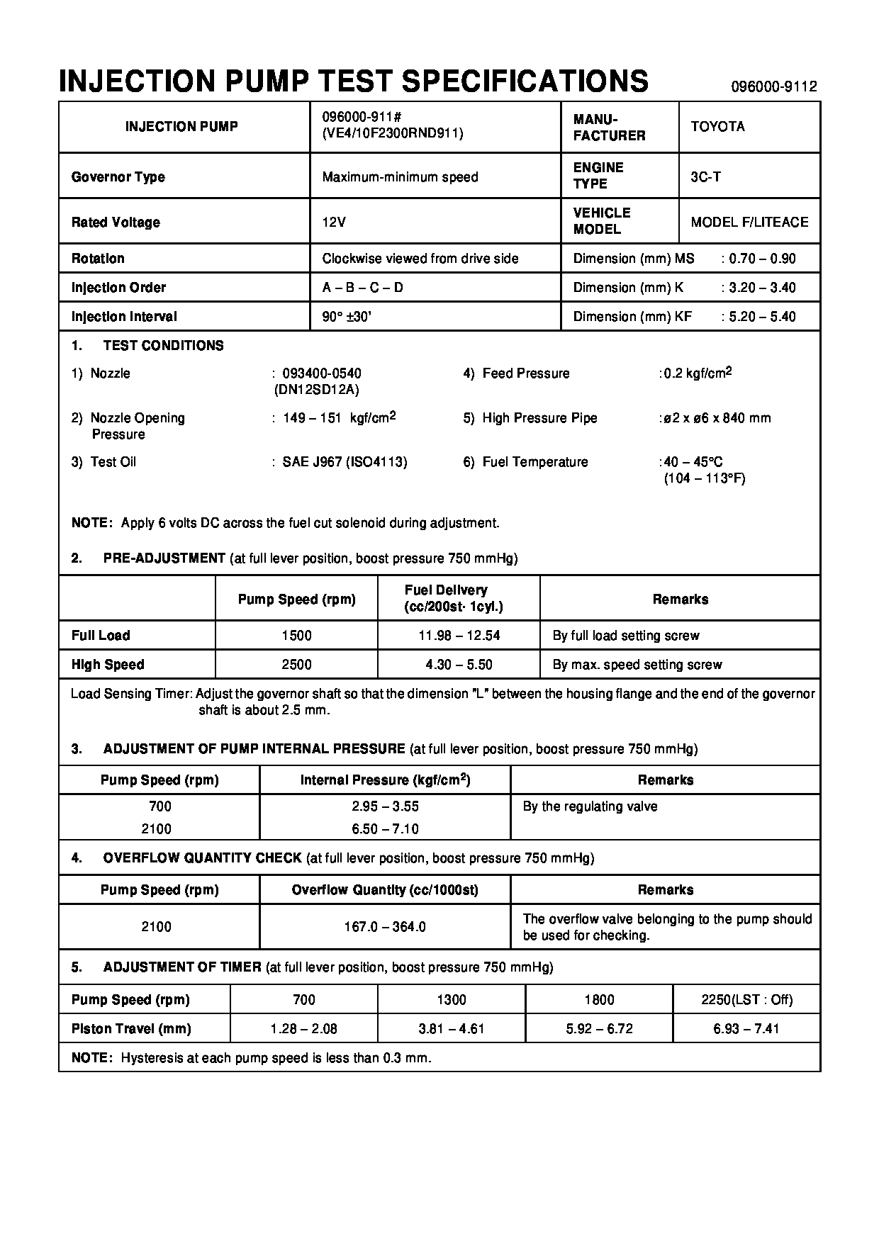
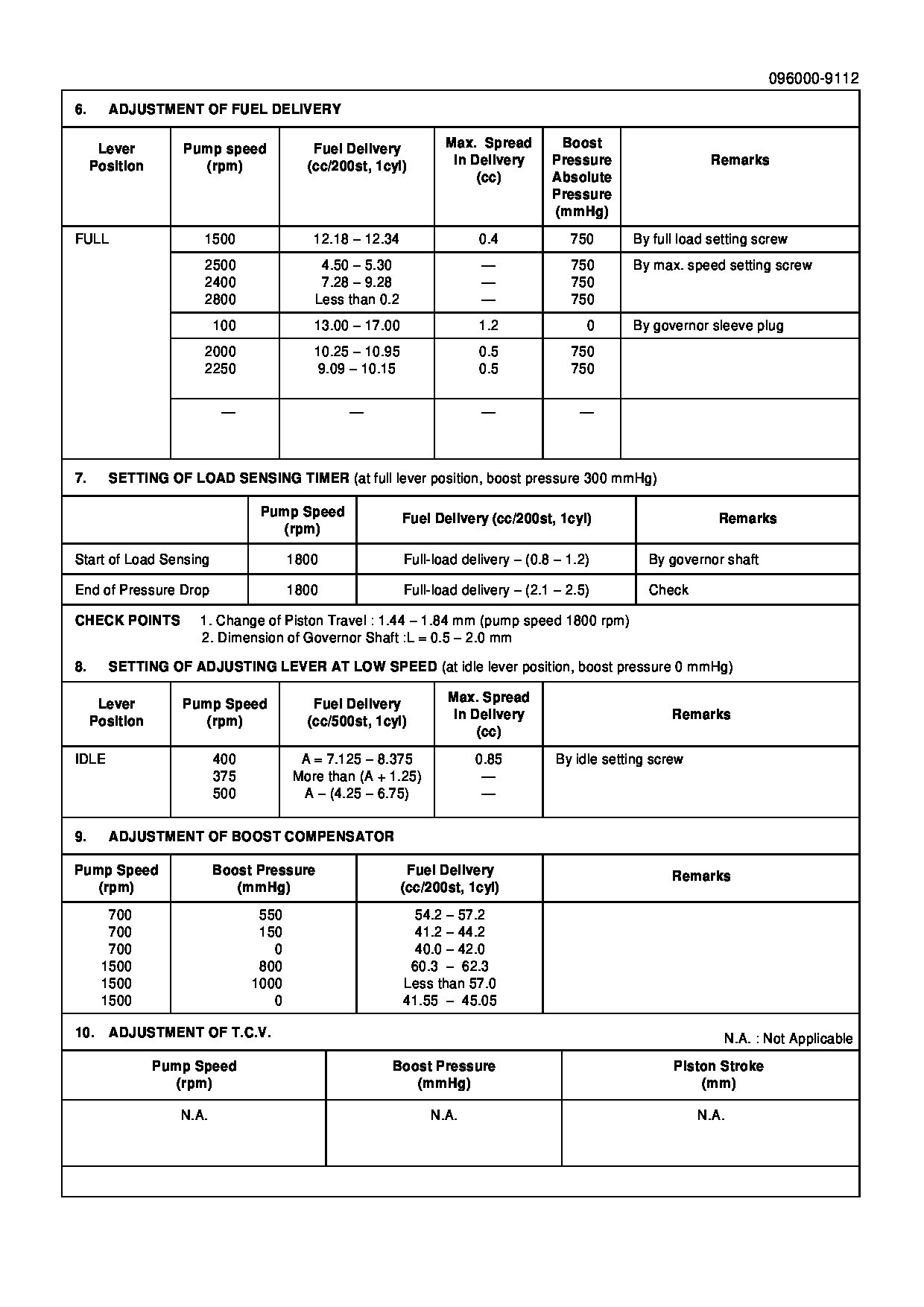
Fuel Injection Pump
Vehicle engine
TOWNACE/LITEACE 3C-T
Engine
3C-T
Serial start-end
9309-
Info
Injector Nozzle
093500-5820
Manufacture:
22100-6D490 TOYOTA
Dim 1
3.2-3.4
Dim 2
5.2-5.4
Dim 3
0.7-0.9
Dim 4
Dim 5
Dim 6
Information
Injector nozzle:
0935005820
KIT List:
Part name
Kit1
Kit2
Cross reference number
Part num
Firm num
Firm
Name
0960009110
22100-6D490
TOYOTA
PUMP ASSY, INJECTI
Information:
Tighten locknuts (A) on rod ends to ... 12 4 N m (9 3 lb ft)With governor at High Idle, install lever (B) on governor shaft at an angle from vertical of ... 20 5°Dimension (C) approximately ... 438.0 mm (17.25 in)Dimension (D) approximately ... 597.0 mm (23.50 in)Dimension (E) approximately ... 610.0 mm (24.00 in)Dimension (F) approximately ... 100.00 mm (3.94 in)Dimension (G) ... 1.5 mm (.06 in)Adjust bolt (H) to get dimension (F) with engine at High IdleAdjust setscrew (J) so that engine speed is 985 50 rpm with decelerator pedal depressed. Check High Idle speed after adjustment.After linkage has been adjusted, move control lever to High Idle and adjust setscrew (K) to get dimension (G).D7G With Direct Drive Transmission & 571G Pipelayer
Tighten locknuts (A) on ends to ... 12 4 N m (9 3 lb ft)With governor at High Idle, install lever (B) on governor shaft at an angle from vertical of ... 20 5°Dimension (C) approximately ... 438.0 mm (17.25 in)Dimension (D) approximately ... 597.0 mm (23.50 in)572G Pipelayer
Tighten locknuts (A) on rod ends to ... 12 4 N m (9 3 lb ft)With governor at High Idle, install lever (B) on governor shaft at an angle from vertical of ... 5° 5°Dimension (C) approximately ... 726.4 mm (28.6 in)Dimension (D) approximately ... 683.3 mm (26.9 in)7G5554 Control Group (D6H)
1. Tighten locknuts (A) on rod ends to ... 14 4 N m (10 3 lb ft)2. Align the timing mark on shaft (B) with centerline of sawcut on lever (C).3. Dimension (D) approximately ... 508 mm (20 in)4. With governor control lever in a vertical position, angle (E) ... 32° 5°3T4347 Control Group (D6H)
1. Tighten locknuts (A) on rod ends to ... 14 4 N m (10 3 lb ft)2. Align the timing mark on shaft (B) with centerline of sawcut on lever (C).3. Dimension (D) approximately ... 508 mm (20 in)4. With governor control lever in a vertical position, angle (E) ... 32° 5°6T3303 Control Group (D7H)
1. Tighten locknuts (A) on rod ends to ... 12 4 N m (9 3 lb ft)2. Align the timing mark on shaft (B) with centerline of sawcut on lever (C).3. With governor control lever in a vertical position, angle (E) ... 32° 5°8P3126 Control Group (D5B SA)
1. With control lever (1) in high idle position Dimension (A) approximately ... 495.0 mm (19.5 in)Dimension (B) approximately ... 786.0 mm (30.9 in)Angle (C) from vertical ... 10° 5°2. Tighten locknuts (2) on rod ends to ... 25 7 N m (18 5 lb ft)3. Tighten locknuts (3) on rod ends to ... 12 4 N m (9 3 lb ft)9W3764 Control Group (D6D SA)
1. With control lever (1) in high idle position Dimension (A) approximately ... 495.0 3.0 mm (19.5 .1 in)Dimension (B) approximately ... 735.0 mm (28.9 in)Angle (C) from vertical