Rating:
Information pump assy, injecti Denso
Product
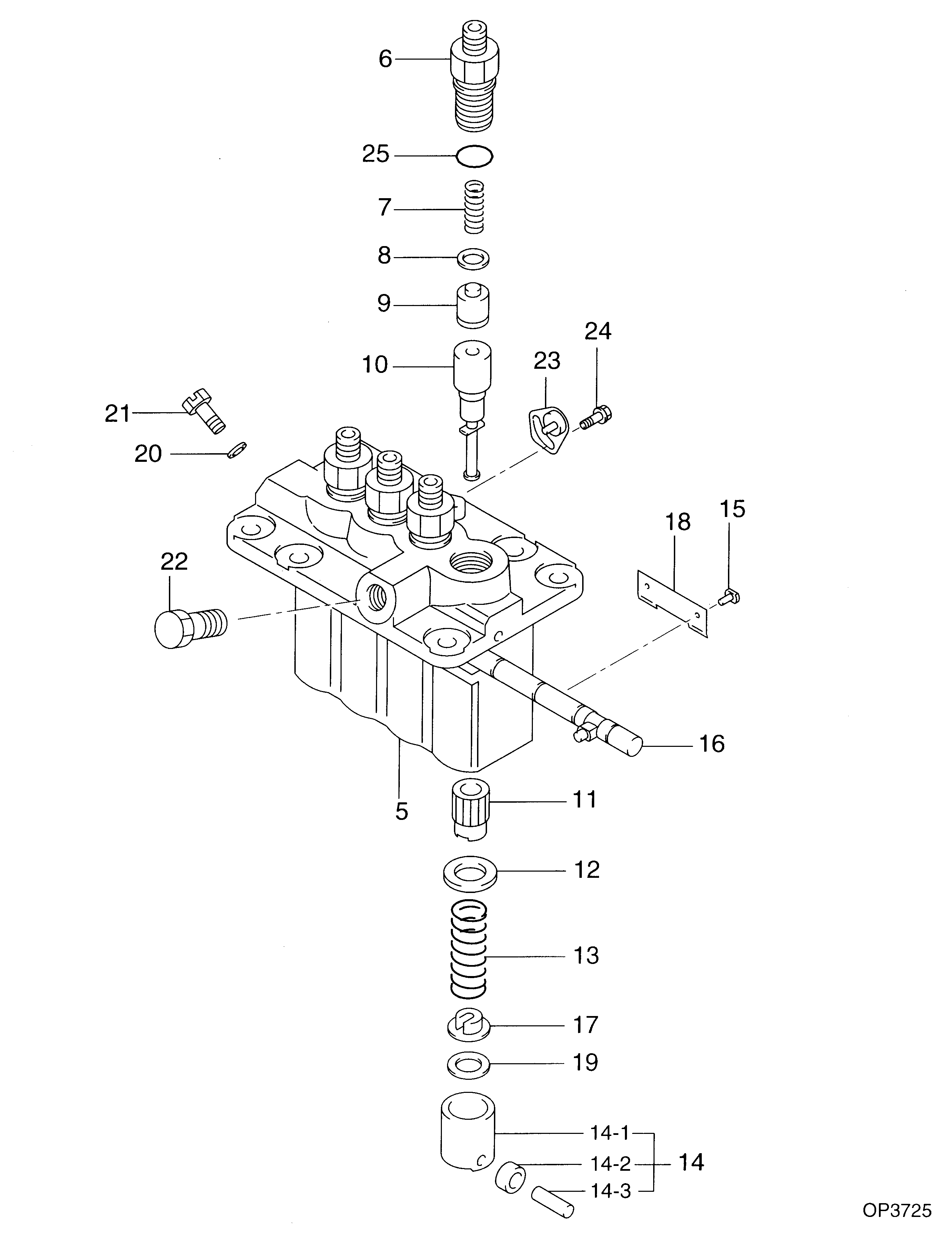
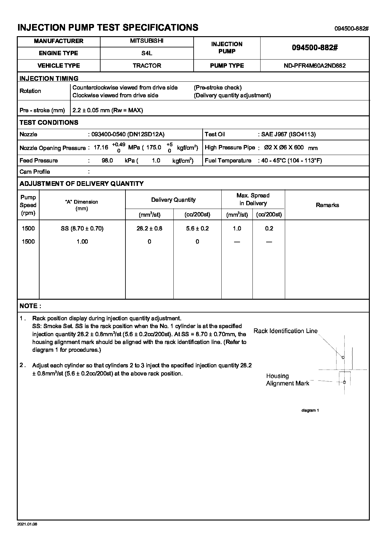
Fuel Injection Pump
Vehicle engine
INDUSTRIAL S4L
Engine
S4L
Serial start-end
Info
Injector Nozzle
093500-3840
Injector nozzle:
0935003840
Components :
Scheme #.#:
№
Qty
Part num
Name
Remarks
Manufacture num
000
[01]
09450-08820
PUMP ASSY, INJECTI
PFR4M
Include in ##:
09450-08820
as PUMP ASSY, INJECTI
Cross reference number
Part num
Firm num
Firm
Name
09450-08820
PUMP ASSY, INJECTI

Information:
1. Position the water pump on the engine.2. Connect the water temperature regulator bypass line.3. Connect water pump outlet line.concluding step: a) install air compressorDisassemble Water Pump
preparatory step: a) remove water pump 1. Remove the water pump cover (1). 2. Loosen the impeller retaining nut flush with the end of the pump shaft. Install tool setup (A) and separate the impeller from the shaft.3. Remove the tool setup and impeller. 4. Remove the bearing cage retaining nuts (3).5. Remove the bearing cage and shaft assembly (2) from the pump housing.6. Remove the ceramic seal and oil seal from the pump housing.7. Remove the bearing retaining nut and spacer from the shaft assembly. 8. Press the gear and bearings from the shaft.Assemble Water Pump
1. Heat the bearings and gear to 300°F (149°C). 2. Install one bearing and its bearing cage (5) on the shaft. Install the gear (4) on the shaft with the concave side towards the bearing cage.3. Install the remaining bearing (3), spacer (2), lock and retaining nut (1). 4. Install the oil seal in the pump housing using tool setup (A). Install the oil seal (8) as shown. 5. Install the ceramic ring (11) and rubber seal (12) in the pump housing with the polished side of the ceramic ring toward the impeller.6. Position the bearing and shaft assembly in the pump housing. Install the bearing cage retaining nuts (7). Lubricate the oil seal lip lightly with SAE 30 engine oil before installing the shaft assembly.7. Install the carbon portion of the seal and the spring on the shaft.8. Install the impeller (10) and retaining nut (6). Tighten the nut to 30 5 lb. ft. (4,1 0,7 mkg) plus the amount required to align on cotter pin hole. Install the cotter pin and bend the legs of the pin around the nut.9. Install the water pump cover (9).concluding step: a) install water pump