Rating:
Information pump assy, injecti Denso
Product
Fuel Injection Pump
Vehicle engine
INDUSTRIAL K3M-D
Engine
K3M-D
Serial start-end
0406-
Info
Injector Nozzle
093500-4320
Injector nozzle:
0935004320
Components :
Scheme #.#:
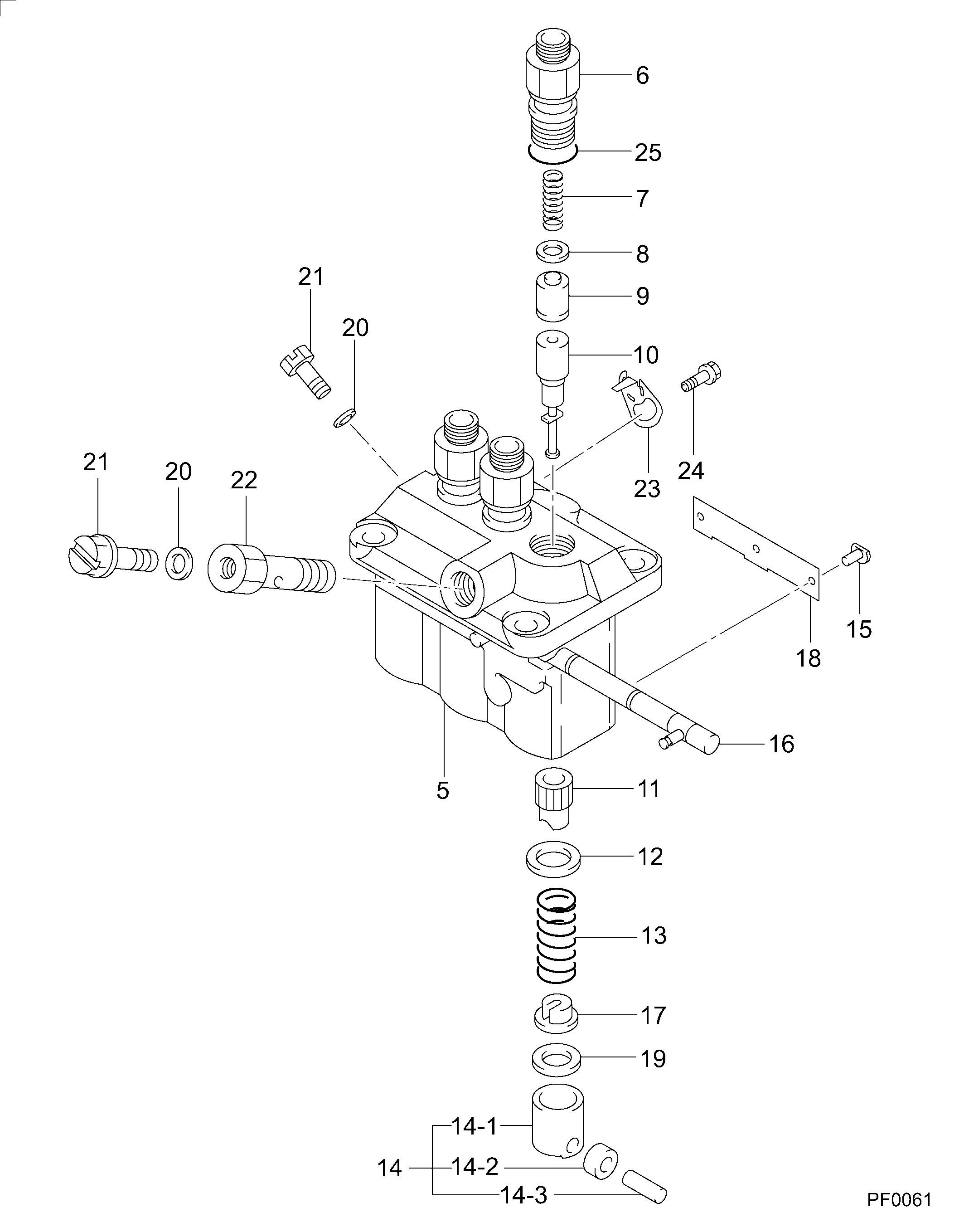
№
Qty
Part num
Name
Remarks
Manufacture num
000
[01]
09450-08390
PUMP ASSY, INJECTI
PFR3M
Include in ##:
09450-08390
as PUMP ASSY, INJECTI
Cross reference number
Part num
Firm num
Firm
Name
09450-08390
PUMP ASSY, INJECTI

Information:
1-Inlet air pipe. 2-Exhaust elbow. 3-Turbocharger oil drain line. 4-Turbocharger oil supply line. 5-Turbocharger. 6-Fuel injection lines (six). 7-Heat shield. 8-Exhaust manifold (three sections).Turbocharger Removal And Installation
Refer to SERVICE GUIDE for Preliminary Information.
1-Exhaust elbow. 2-Turbocharger oil supply line. 3-Bolts and nuts (two each). 4-Bolts, locks and nuts (four each). 5-Turbocharger oil drain line. 6-Inlet air pipe. Apply 9M3710 Anti-Seize Compound to threads of bolts (3 and 4) when installing turbocharger.Turbocharger Disassembly And Assembly
8S9944 Turbine Holder.1,3,5 Remove nut (1). Position the compressor end of housing (5) in an oil bath so only impeller (3) is immersed in oil. Heat impeller to 350° F. (176° C.) for not longer than ten minutes. Remove unit from oil bath and press the shaft and turbine wheel from impeller (3).1,3,5 At installation, heat impeller (3) to a maximum of 350°F. (176°C.) for not longer than ten minutes and proceed as follows: For ease of impeller installation, place the turbine wheel end of center housing (5) in an 8S9944 Turbine Holder.a. Immediately install impeller (3) on shaft, install nut (1) and tighten it to 120 lb. in. (138,4 cm.kg).b. Allow impeller to cool to less than 150°F. (65, 49°C.) and remove nut (1).c. Clean and smooth the washer face of nut (1). Lightly oil the threads of turbine shaft and nut and install the nut.d. Tighten nut (1) to 20 lb. in. (23,0 cm.kg), then tighten an additional 120°.2 Coat threads with 9M3710 Anti-Seize Compound.4,5 Install thrust plate assembly (4) so oil hole aligns with oil hole in housing (5).