Rating:
Information pump assy, injecti Denso
Product
Fuel Injection Pump
Vehicle engine
INDUSTRIAL S4L
Engine
S4L
Serial start-end
0406-
Info
Injector Nozzle
093500-3840
Injector nozzle:
0935003840
Components :
Scheme #.#:
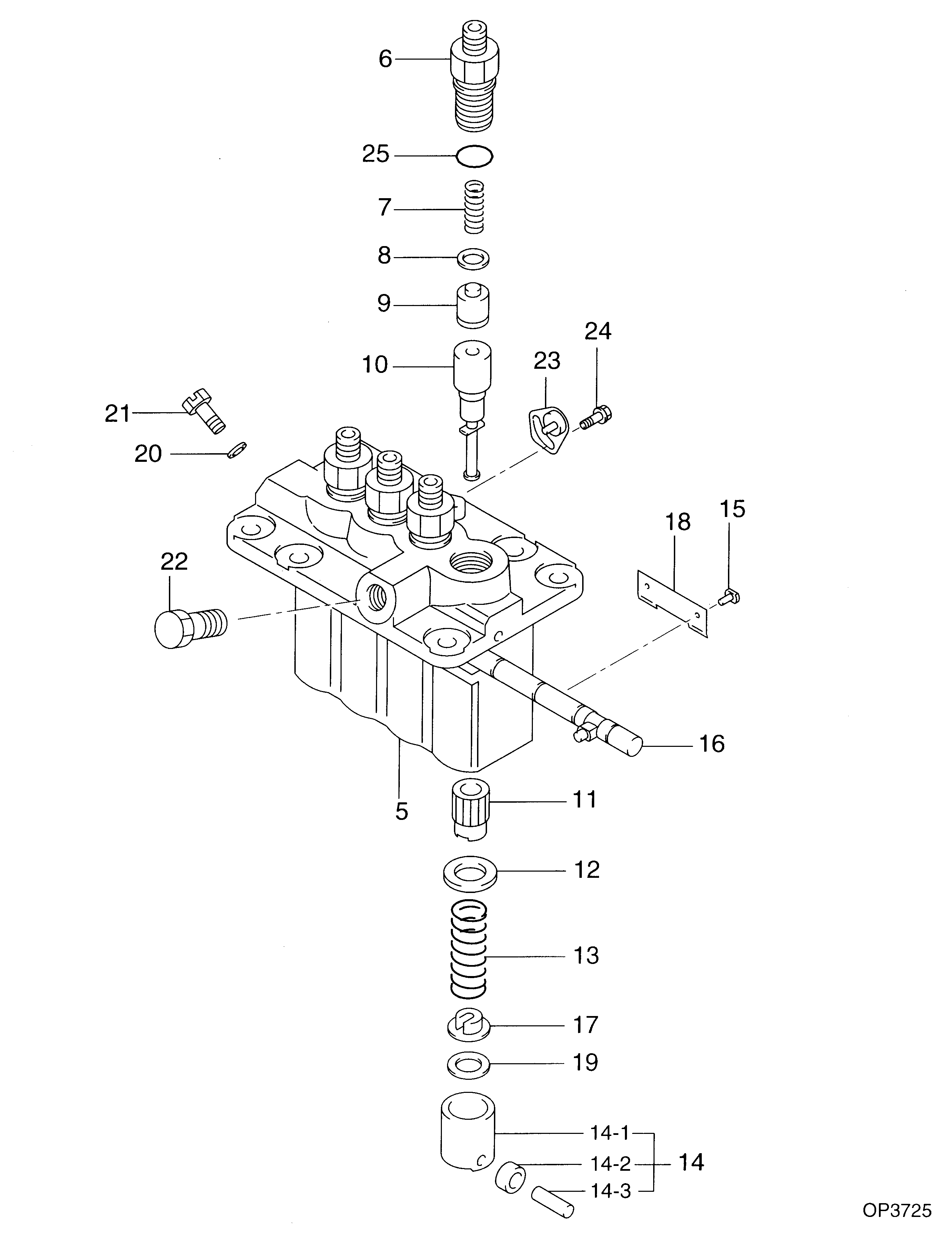
№
Qty
Part num
Name
Remarks
Manufacture num
000
[01]
09450-08350
PUMP ASSY, INJECTI
PFR4M
Include in ##:
09450-08350
as PUMP ASSY, INJECTI
Cross reference number
Part num
Firm num
Firm
Name
09450-08350
PUMP ASSY, INJECTI

Information:
1. Remove suction bell (3) and tubes, oil supply tube (2) and BrakeSaver oil supply tube (1) from the engine block and oil pump. 2. Remove three bolts (5) and oil pump (4) from the engine. The following steps are for installation of the oil pump.3. Put oil pump (4) in position on the engine. Make sure the oil pump gear is engaged with the crankshaft gear and install three bolts (5) that hold the oil pump.4. Put clean oil on the O-ring seals on the oil tubes.5. Install suction bell (3) and tubes, oil supply tube (2) and BrakeSaver oil supply tube (1).end by:a) install oil pan (BrakeSaver)Disassemble Oil Pump (Brakesaver)
start by:a) remove oil pump (BrakeSaver) 1. Remove the bolt and washer that hold drive gear (1) on the shaft.2. Use tooling (A) to remove drive gear (1) from the shaft. Remove the key from the shaft. Put marks on the pump bodies so they can be assembled in the correct position. 3. Remove retainer (3) for the bypass valve. Remove the spring and bypass valve.4. Remove bolts (4) that hold pump body (2) to the main pump body. Remove pump body (2).5. Use tooling (B) to remove the bearings from pump body (2). 6. Remove gears (7). Put marks on the gears so they can be assembled in the same position.7. Remove spacer (6) from main oil pump body (5). Use tooling (B) to remove the bearings from spacer (6).8. Remove the gears from main oil pump body (5). 9. Use tooling (B) to remove the bearings from the main oil pump body.Assemble Oil Pump (Brakesaver)
1. Use tooling (A) to install bearings (2) until they are even with the outside surface of main oil pump body (1). Install bearings (2) so the junctions in the bearings are 30° 15° from the center line of the bearing bores and toward the oil pump outlet passage as shown. 2. Use tooling (A) to install bearings (3) in the spacer. Install the bearings until they are in position an equal distance in from each side of the spacer. Install the bearings with the oil holes in the bearings in alignment with the oil holes in the spacer and the junctions in the bearings in alignment with the cavity in the spacer as shown. 3. Put clean engine oil on all the gears and bearings before they are assembled in the oil pump. Install idler and drive gears (5) in the main oil pump body.4. Install spacer (4) on the gear shafts with the smaller cavity out and the oil holes in the spacer toward the pump outlet passage as shown. 5. Use tooling (A) to install bearings (6) in pump body (7) until they are .060 .010 in. (1.52 0.25 mm) from the inside edge of the bearing bores. Install the bearings so the junctions in the bearings are 30° 15° from the center line of the bearing bores and toward the outlet passage. The