Rating:
Information pump assy, injecti Denso
Product
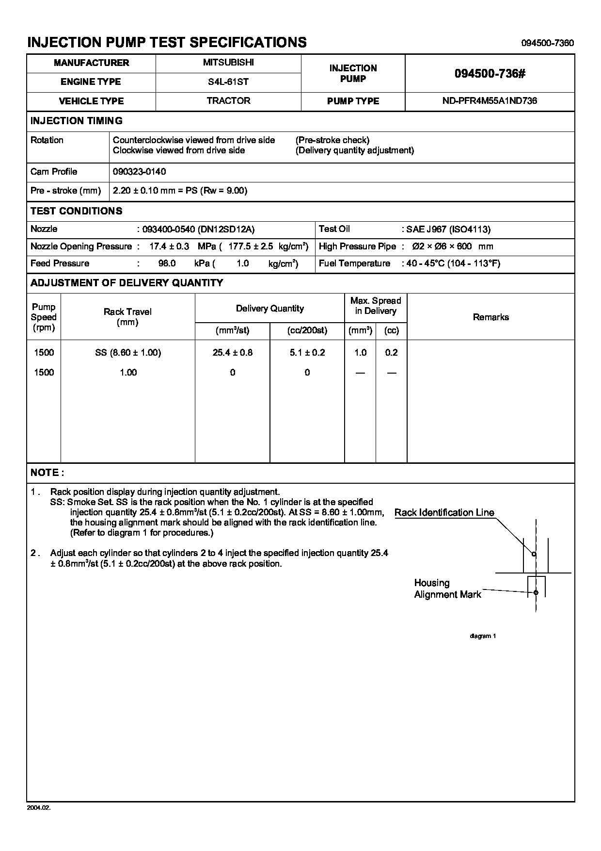
Fuel Injection Pump
Vehicle engine
agricultural machine S4L-T61ST
Engine
S4L-T61ST
Serial start-end
9802-
Info
Injector Nozzle
093500-3840
Injector nozzle:
0935003840
Components :
Scheme #.#:
№
Qty
Part num
Name
Remarks
Manufacture num
000
[01]
09450-07360
PUMP ASSY, INJECTI
PFR4M
Include in ##:
09450-07360
as PUMP ASSY, INJECTI
Cross reference number
Part num
Firm num
Firm
Name
09450-07360
PUMP ASSY, INJECTI

Information:
Before any service work is to be done on the fuel system the outer surface of the injection pump housing must be clean.
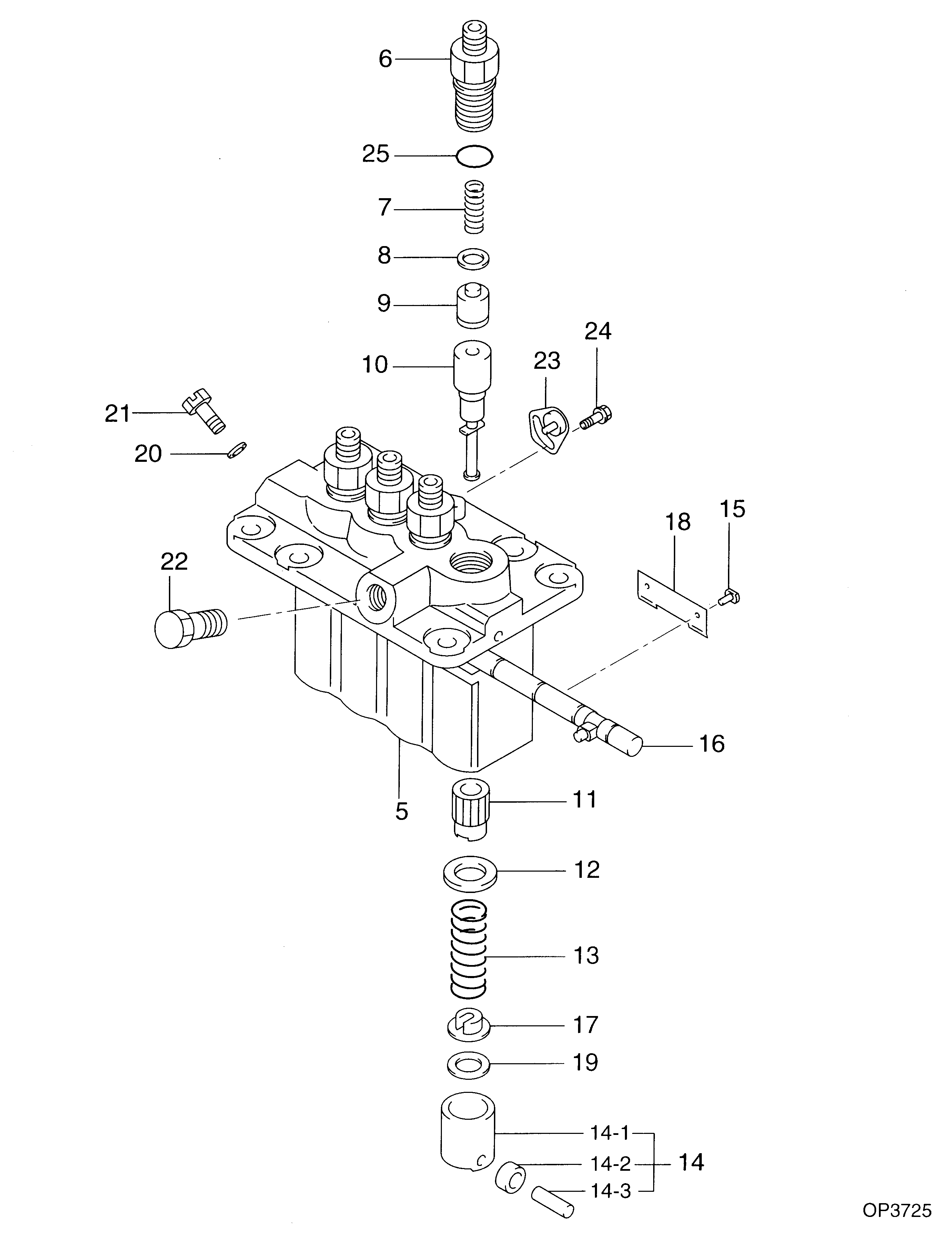
1. Remove cover assembly (1) from the pump housing. Remove the spring for the bypass valve. 2. Loosen bushing (2) from the pump housing with tool (A). Do not loosen screws (3) when removing or installing the pumps. If the levers are moved, the fuel pump adjustment will be changed.3. Remove the fuel injection pump from the pump housing. The sleeve on the plunger will slide off the lever as the pump is removed.Install Fuel Injection Pumps
1. Put fuel injection pump (1) in the bore of the pump housing.2. Sleeve (2) must be engaged with lever (3) when installed correctly.
If the levers (3) have been moved on the shaft, fuel pump adjustment must be made. (See TESTING AND ADJUSTING).
3. Tighten the bushing with tool (A) to a torque of 70 5 lb.ft. (95 7 N m). 4. Put the spring and bypass valve in place. Install the cover assembly on the pump housing. Be sure spring (4) is in position in the cover.Disassemble Fuel Injection Pumps
start by: a) remove fuel injection pumps1. Remove bushing (1) from bonnet (2).2. Remove ring (3) from the bonnet and barrel (7). Remove check valve (6) and spring (4) from the bonnet.3. Remove spring (8) and washer (5). Remove plunger (9) and sleeve (10). Keep the plunger and sleeve with their respective barrel for installation. Do not use plungers, sleeves or barrels with other plungers, sleeves or barrels.Assemble Fuel Injection Pumps
1. Install sleeve (4), plunger (5), spring (2) and washer (3) on barrel (1).
Make sure the sleeve is installed with the thin edge up.
Be sure the sleeve and plunger are installed in their original barrel. Make sure the large hole in the plunger is up.2. Install the check valve and spring in the bonnet. Connect the barrel and bonnet and install the ring. Install the bushing on the bonnet.end by: a) install fuel injection pumps