Rating:
Information pump assy, injecti Denso
Product
Fuel Injection Pump
Vehicle engine
INDUSTRIAL OC60-EDI-Q
Engine
OC60-EDI-Q
Serial start-end
9310-
Info
Injector Nozzle
093500-4660
Injector nozzle:
0935004660
Compare Prices: .
As an associate, we earn commssions on qualifying purchases through the links below

1G131-51012 094500-6630 Fuel Injection Pump Replacement for Kubota OC60 KC70 Engine
WZCPSM Product Name:Fuel Injection Pump || Product Number:1G131-51012 094500-6630 || Application:Replacement for Kubota OC60 KC70 Engine || Note: Please verify your part number before purchasing. If you are unsure, please contact us. Thank you for your cooperation. || Tip: This product has fast response stable performance, high reliability, easy installation .It has been repeatedly tested and is of high quality and the most guaranteed.
WZCPSM Product Name:Fuel Injection Pump || Product Number:1G131-51012 094500-6630 || Application:Replacement for Kubota OC60 KC70 Engine || Note: Please verify your part number before purchasing. If you are unsure, please contact us. Thank you for your cooperation. || Tip: This product has fast response stable performance, high reliability, easy installation .It has been repeatedly tested and is of high quality and the most guaranteed.

Denso Injection Pump 1G131-51012 094500-6630 Suitable for Kubota OC60 KC70
Teaviatorial 🔥Part Name:Denso Injection Pump || 🔥Part Number:1G131-51012 094500-6630 || 🔥Application:for Kubota OC60 KC70 || 🔥Attention: If you are unsure if the product is suitable for your machine model. In order not to delay your use of the parts, please provide your engine nameplate or serial number and part number, and we will help you confirm if it is suitable. To avoid unnecessary returns, please carefully check the product image and part number to ensure that it is the product you want. Thank you for your support and understanding! || 🔥Tip: If you need any other parts, please contact us - we are a professional sales team and have many products to offer to you. Many buyers are very satisfied with our service. You can get first-class products and high-quality services from us, believe me, you will have a pleasant shopping experience here.
Teaviatorial 🔥Part Name:Denso Injection Pump || 🔥Part Number:1G131-51012 094500-6630 || 🔥Application:for Kubota OC60 KC70 || 🔥Attention: If you are unsure if the product is suitable for your machine model. In order not to delay your use of the parts, please provide your engine nameplate or serial number and part number, and we will help you confirm if it is suitable. To avoid unnecessary returns, please carefully check the product image and part number to ensure that it is the product you want. Thank you for your support and understanding! || 🔥Tip: If you need any other parts, please contact us - we are a professional sales team and have many products to offer to you. Many buyers are very satisfied with our service. You can get first-class products and high-quality services from us, believe me, you will have a pleasant shopping experience here.

1G131-51012 094500-6630 Fuel Injection Pump Compatible for Kubota OC60 KC70 Engine
JPSMZSC Product Name:Fuel Injection Pump || Part number:1G131-51012 094500-6630 || Application:Compatible for Kubota OC60 KC70 Engine || Note: Please confirm that the product shown in the part number is what you need. If you cannot confirm, you can leave us a message and provide your engine serial number and nameplate. || Tip: We mainly deal in all parts of the construction machinery series. Our product has stable performance, fast response, high reliability, and easy installation. High quality, most guaranteed. If you have any other requirements, please contact us.
JPSMZSC Product Name:Fuel Injection Pump || Part number:1G131-51012 094500-6630 || Application:Compatible for Kubota OC60 KC70 Engine || Note: Please confirm that the product shown in the part number is what you need. If you cannot confirm, you can leave us a message and provide your engine serial number and nameplate. || Tip: We mainly deal in all parts of the construction machinery series. Our product has stable performance, fast response, high reliability, and easy installation. High quality, most guaranteed. If you have any other requirements, please contact us.
You can buy:

Components :
Scheme #.#:
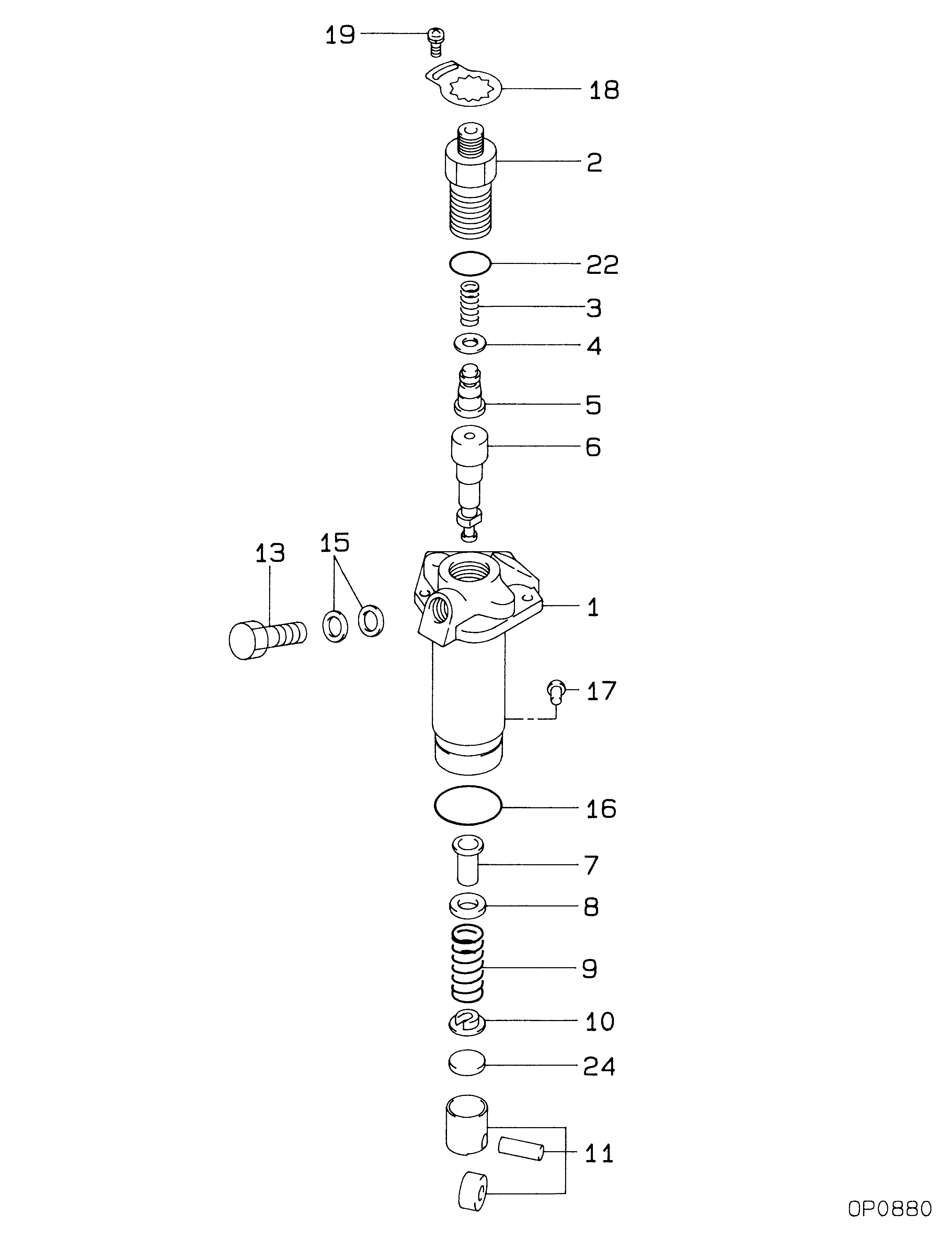
№
Qty
Part num
Name
Remarks
Manufacture num
000
[01]
09450-06630
PUMP ASSY, INJECTI
PFR1NC
1G131-51012
KUBOTA
Include in ##:
09450-06630
as PUMP ASSY, INJECTI
Cross reference number
Part num
Firm num
Firm
Name
09450-06630
1G131-5101
PUMP ASSY, INJECTI
0945006630
1G131-51012
KUBOTA
PUMP ASSY, INJECTI

Information:
1. Remove strainer (2) from governor cover (1). 2. Bend the locks back and remove four bolts (6). Remove levers (4) and (5).3. Remove shaft (3) and the washer from the governor cover. 4. Remove two bearings (7) and two seals (8) from the governor cover with tooling (A). 5. Remove insulator (9) from governor cover (1). 6. Put a mark on the high idle screw (10) and make a note of each turn until the idle screw is removed from governor housing (13). This is done to get the approximate setting for assembly purposes. Remove the O-ring seal from the idle screw.
Do not mix the sequence of insulators, shims, spacers, contact, bar and spring. For more information see FUEL SETTING INFORMATION Fiche SBFY1106. The sequence of these parts can be different between engines. Bend lock (11) down and remove the two bolts. Remove torque spring group (12). Remove lock, retainer, insulator, spacer, contact, spring, spacer, shim, bar and insulator.
8. Bend the lock down and remove bolt (15) from control lever (14). Remove shaft (16) and control lever (14) from the governor housing. 9. Remove band assembly (17) from control lever (14).
Care must be taken when pin (18) is removed. The spring and plunger behind pin (18) are under spring force.
10. Remove pin (18), spring and plunger from control lever (14). 11. Remove bearings (19) and two seals (20) from governor housing (13). 12. Remove seat (21), spring washer (22), flat washer (24), spring washer (23) and spring (25). 13. Remove washer (27) from governor bolt (26).14. Remove ring (28) from seat (29). 15. Remove dowel (30) from seat (29). Remove seat (29) and governor bolt (26) as a unit. Remove bolt (26) from seat (29). 16. Remove washer (31), spring (32), washer (33) and sleeve (34) from the servo piston valve. 17. Remove ring (38), large race (37), bearing (35) and small race (36) from sleeve (34). 18. Remove lock (40) from flyweight assembly (39). Remove flyweight assembly (40). 19. Bend the locks from bolts (41) and remove bolts (41).20. Remove bracket (42) and the servo piston assembly as a unit. 21. Remove piston (44) from pin (43). Remove pin (43) from bracket (42). 22. Remove sleeve (45) and valve (46) from piston (44). Remove O-ring seal (47) from sleeve (45). 23. Remove shaft (48) from bracket (42) with a hammer and punch.24. Remove lever (49) from bracket (42). 25. Hit (tap) lightly on cylinder (50) to remove it from the governor plate. 26. Remove O-ring seals (51) from cylinder (50). 27. Remove spiral ring (53), and then remove dowel (52) behind the spiral ring. 28. Remove drive assembly (54) and stop (55) from drive gear (56). 29. Turn the governor plate over and remove snap ring (57) from drive gear (56) with tool (B).30. Remove drive gear (56) from the governor plate. 31. If a replacement is needed, remove dowels (59), (60) and (61).32. Remove bearing (58) from the governor plate with tooling (A).Assemble Governor
1. If