Rating:
Information pump assy, injecti Denso
Product
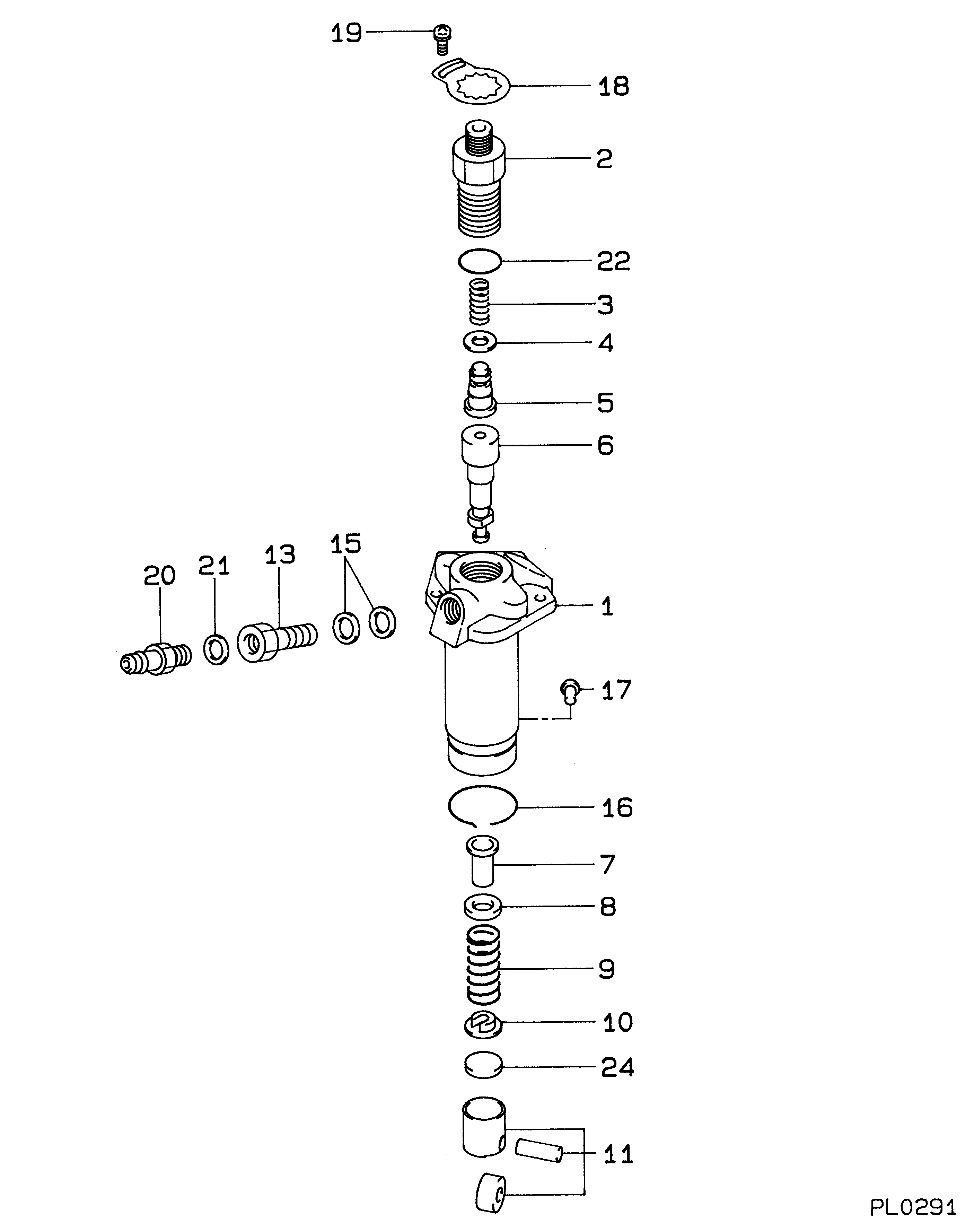
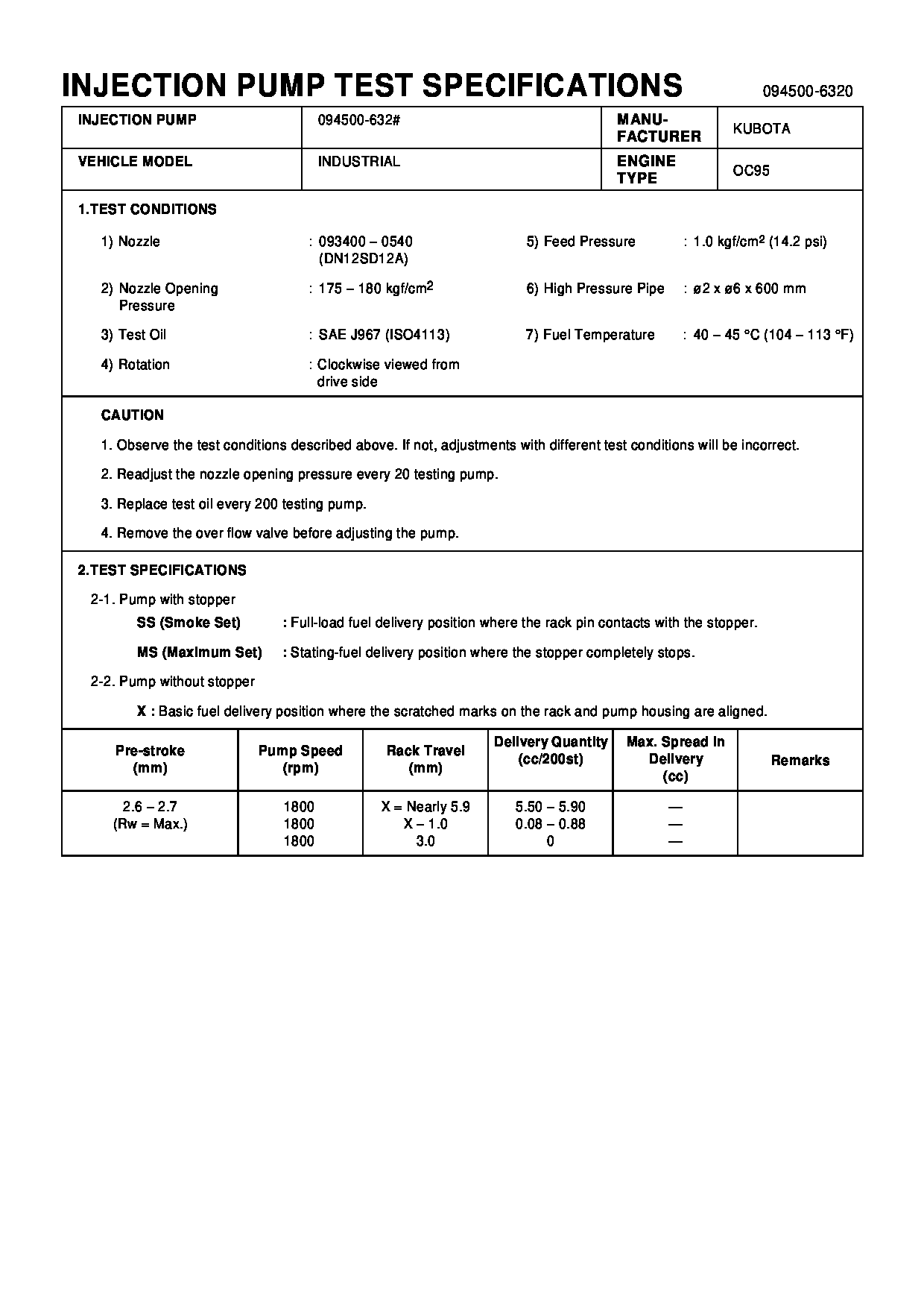
Fuel Injection Pump
Vehicle engine
INDUSTRIAL OC95-D
Engine
OC95-D
Serial start-end
9304--9803
Info
Injector Nozzle
093500-4660
Injector nozzle:
0935004660
Components :
Scheme #.#:
№
Qty
Part num
Name
Remarks
Manufacture num
000
[01]
09450-06320
PUMP ASSY, INJECTI
PFR1NC
11469-51011
KUBOTA
Include in ##:
09450-06320
as PUMP ASSY, INJECTI
Cross reference number
Part num
Firm num
Firm
Name
09450-06320
11469-5101
PUMP ASSY, INJECTI
0945006320
11469-51011
KUBOTA
PUMP ASSY, INJECTI

Information:
Positioning Pin Bearing (Type A)Type A (Narrow Taper) - Bearing junction and locating hole are 180° apart (directly across from each other). Bearing junction and locating hole must be assembled within either area "A" (90 10° from centerline through the connecting rod bores) as shown.
Positioning Pin Bearing (Type B)Type B (Wide Taper) - Bearing junction and locating hole are 155° apart (not directly across from each other). Bearing junction and locating holes must be assembled in the top half of connecting rod eye area "A" (12.5 1° above the horizontal centerline) as shown.Make reference to Special Instruction Form No. SMHS7295 for use of pin bearing removal and installation tools and procedures.(2) Bore in connecting rod for bearing with nuts tight to specifications (6) ... 103.500 0.013 mm (4.0748 .0005 in.)(3) Distance between center of bearings ... 261.62 0.05 mm (10.300 .002 in.)(4) Bore in bearing for piston pin (new) ... 50.830 0.008 mm (2.0012 .0003 in.)Diameter of piston pin (new) ... 50.795 0.005 mm (1.9998 .0002 in.)Maximum permissible clearance between bearing and piston pin (worn) ... 0.08 mm (.003 in.)(5) Bore in bearing for crankshaft ... 97.119 to 97.175 mm (3.8236 to 3.8258 in.)Clearance between bearing and crankshaft (new) ... 0.071 to 0.168 mm (.0028 to .0066 in.)Maximum permissible clearance between bearing and crankshaft (worn) ... 0.25 mm (.010 in.) Bearings are available in 0.63 mm (.025 in.) and 1.27 mm (.050 in.) smaller than original size.
Marks For Tightening Connecting Rod Bolts(6) Tightening procedure for connecting rod bolts:a. Put 2P2506 Thread Lubricant on bolt threads and contact surfaces of nut and cap.b. Tighten both nuts to ... 80 8 N m (60 6 lb.ft.)c. Put a mark on each nut and end of bolt as shown.d. Tighten each nut from mark ... 120 5° The connecting rod must be installed so the chamfer on the edge of bore (5) is near the corner on the crankshaft. The side opposite the chamfered edge must be against the other connecting rod on the same crankshaft pin.Side clearance between two connecting rods on the same crankshaft pin (new) ... 0.28 to 0.84 mm (.011 to .033 in.)Make reference to Special Instruction Form Nos. GMG02394 & SMHS7366 for information to check and recondition connecting rods. Also see, Guideline For Reusable Parts; Salvage Of Non-Serrated Connecting Rods, Form No. SEBF8064.