Rating:
Information pump assy, injecti Denso
Product
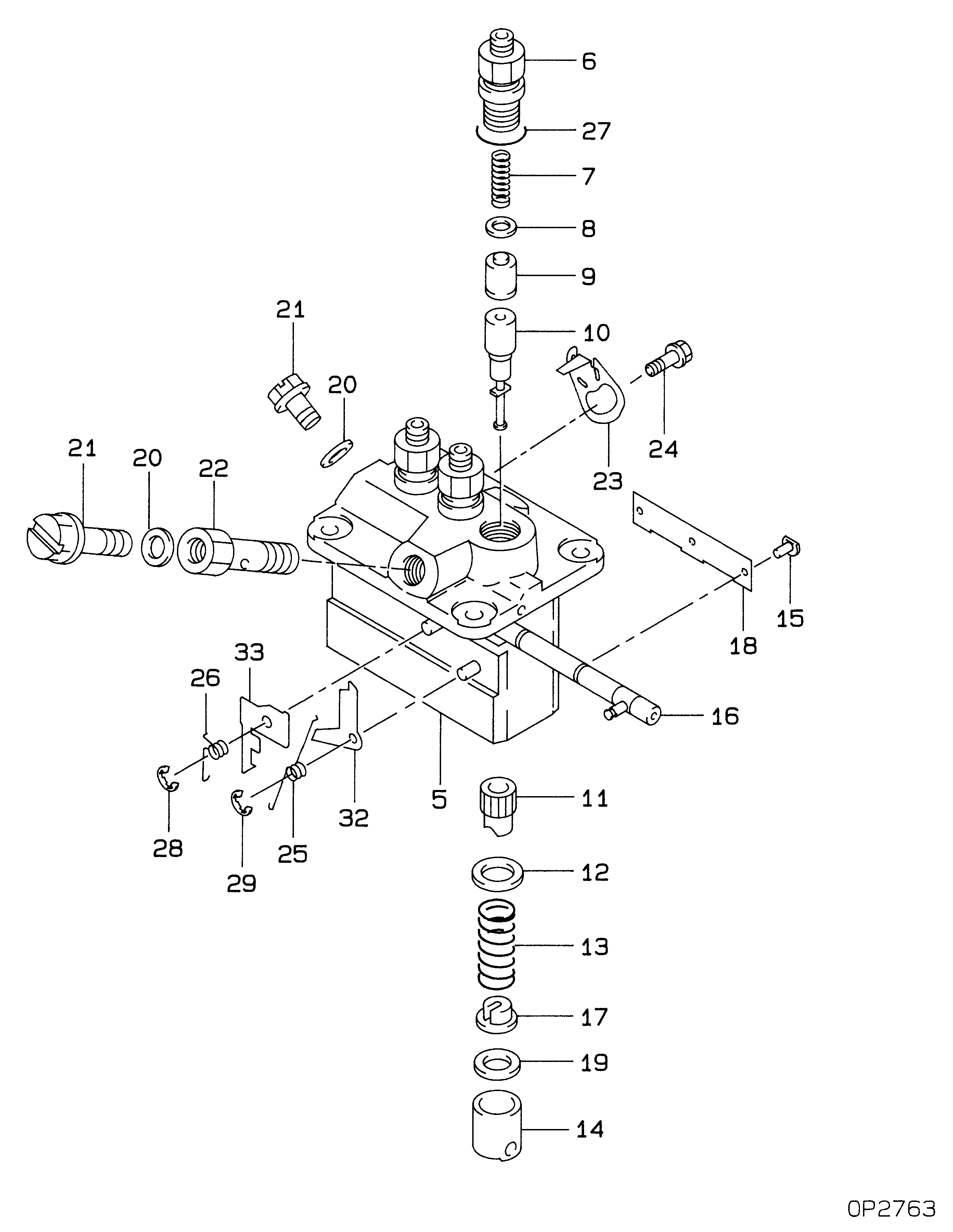
Fuel Injection Pump
Vehicle engine
Construction machine K3H
Engine
K3H
Serial start-end
8301--9108
Info
Injector Nozzle
093500-2300
Injector nozzle:
0935002300
Components :
Scheme #.#:
№
Qty
Part num
Name
Remarks
Manufacture num
000
[01]
09450-02500
PUMP ASSY, INJECTI
PFR3M
Include in ##:
09450-02500
as PUMP ASSY, INJECTI
Cross reference number
Part num
Firm num
Firm
Name
09450-02500
PUMP ASSY, INJECTI


Information:
3. Remove bearing caps (1) from the two connecting rods. Put pieces of rubber hose or tape on the threads of the connecting rod bolts as protection for the crankshaft. 4. Push the pistons up until the piston rings are clear of the cylinder liner. Remove pistons (2). Keep each cap with the respective connecting rod.
Do not turn the crankshaft while any of the connecting rods are in the engine without the caps installed. Do not damage the cooling tubes when the pistons are removed.
Install Pistons
1. Put clean engine oil on the piston rings, connecting rod bearings and cylinder liners. 2. Put two pistons in position opposite of each other in the correct bore of the block. install pistons (1) with Tool (A).
Be sure the pistons are installed with flat surfaces (2) of the connecting rods toward each other and the chamfered sides (4) toward the crankshaft.
For more detail about installation of connecting rod bearings, see remove and install connecting rod bearings.3. Check the bearing clearance with Plastigage (B).
Do not use an impact wrench to tighten the nuts the additional 120 degrees.
4. Put clean engine oil on bolts (5). Install caps (3) and nuts finger tight. Tighten each nut to a torque of 80 8 N m (60 6 lb ft). Put a mark across the nuts and bolts. Tighten each nut 120 degrees more.5. Check the side clearance between two connecting rods on the same crankshaft journal. Clearance must be 0.28 to 0.84 mm (.011 to .033 in) for new rods.End By:a. install oil pumpb. install cylinder headsDisassemble & Assemble Pistons
Start By:a. remove pistons 1. Remove bearing halves (2) from the connecting rod and connecting rod cap. New retainer rings allow the use of pliers to remove retainer rings (1).2. Use Tool (C) or pliers to remove retainer rings (1) from each side of the piston. Remove pin (3) and the connecting rod from the piston. 3. Use Tool (A) to remove the piston rings from piston (4). 4. Heat the connecting rod to a temperature of 177° - 204°C (350° - 400°F). Put 5P-8651 Spacer (12) in the base plate. Put connecting rod in position on the base plate of Tooling (B).5. Put the connecting rod piston pin bearing end in the center of the port assembly of Tooling (B). Install pin (8) in the center of the bore for the connecting rod bearings.6. Install 5P-8650 adapter (10). Put the hole in the adapter in alignment with the hole in the base plate of Tooling (B).7. Install clamp bar (11) and clamp pin (7).8. Install new piston pin bearing (6) on adapter (10). The old bearing is pushed out by Tooling (B) as the new bearing is installed.9. Put 5P8649 Adapter (9) in position as shown with the taper side down. The piston pin bearing joint must be in alignment with the hole in adapter (10) and the base plate of Tooling (B).10. Put pusher (5) on adapter (9).11. Use Tooling (B) to push