Rating:
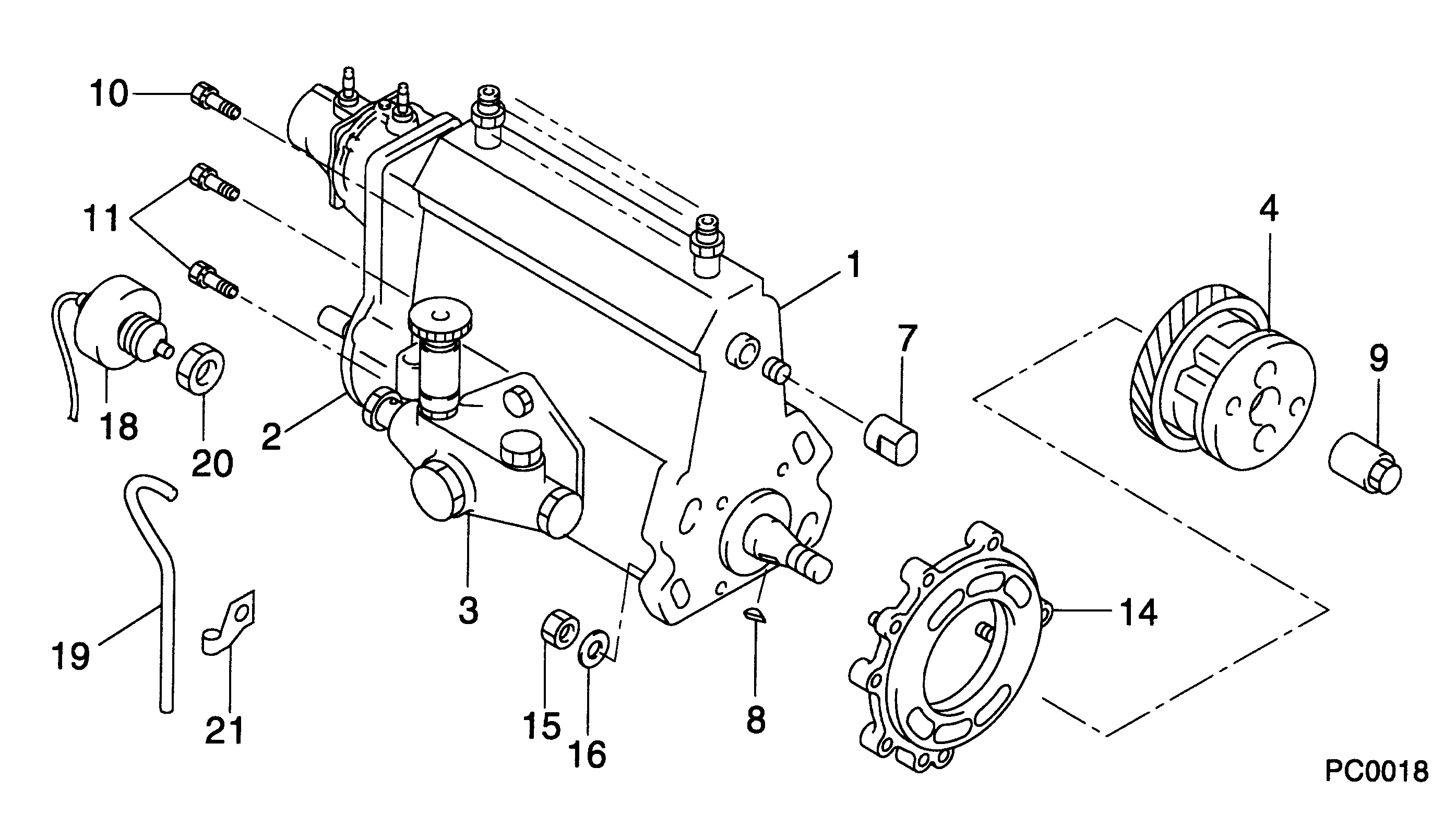
Information pump assy, injecti Denso
Components :
Scheme #.#:
№
Qty
Part num
Name
Remarks
Manufacture num
000
[01]
09300-00361
PUMP ASSY, INJECTI
A6,COMB
22010-68061
TOYOTA
Include in ##:
09300-00361
as PUMP ASSY, INJECTI
Cross reference number
Part num
Firm num
Firm
Name
09300-00361
22010-6806
PUMP ASSY, INJECTI
Information:
1. Disconnect hose (1) at governor control cylinder (2).2. Remove pin (4).3. Remove governor control cylinder (2).4. Note the position of linkage (3) in the lever, and remove linkage (3). The following steps are for installation of the governor control cylinder.5. Adjust linkage (3) so the distance between rod end centers is 84.07 mm (3.309 in).6. Install linkage (3) in its original position in the lever.7. Be sure lever (5) on the governor shaft is at 15 degrees from vertical (CW when viewed from the left side of the machine) with engine at low idle.8. Install control cylinder (2). Install pin (4) through link (3) and lever (5).9. Connect hose (1) to governor control cylinder (2).10. Adjust linkage (3) so lever (5) is at low idle when governor control cylinder is fully retracted.Disassemble & Assemble Governor Control Cylinder
Start By:a. remove governor control cylinder 1. Remove cover (1).
A spring force of 44.5 N (10 lb) will be released when the bolt that holds piston (8) is removed. Hold the components of the governor control cylinder to prevent unexpected movement of components and personal injury.
2. Remove the bolt that holds piston (6), and remove the piston and springs.3. Remove O-ring seal (2) and sleeve (5).4. Remove seals (3) and (4) from piston (6). The following steps are for the assembly of the governor control cylinder.5. Install lip-type seal (3) and "T" seal on the piston (6). Install the lip-type seal with the lip facing the cylinder pressure source.6. Install shell (5) in the air chamber body.7. Put 5P-0960 Multipurpose Grease inside the shell.8. Carefully install piston (6) and springs into the air chamber body.9. Install the bolt to hold the piston.10. Install O-ring seal (2) and cover (1).End By:a. install governor control cylinder