Rating:
Information pump assy, injecti Denso
Product
Fuel Injection Pump
Vehicle engine
LAND CRUISER 2H
Engine
2H
Serial start-end
8201--8410
Info
Injector Nozzle
093500-2370
Injector nozzle:
0935002370
KIT List:
Part name
Kit1
Kit2
Components :
Scheme #.#:
№
Qty
Part num
Name
Remarks
Manufacture num
000
[01]
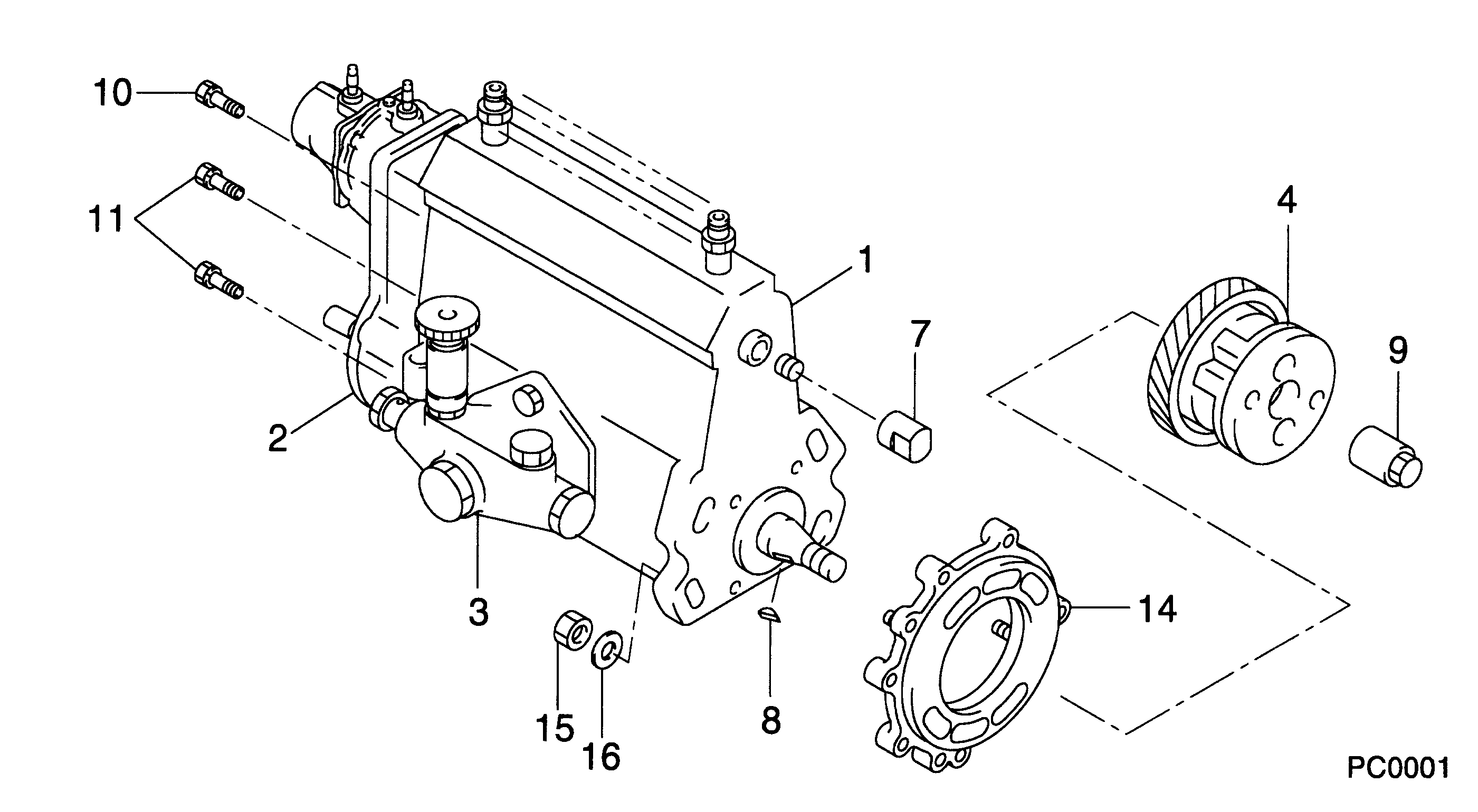
09300-00350
PUMP ASSY, INJECTI
A6,COMB
22010-68051
TOYOTA
Include in ##:
09300-00350
as PUMP ASSY, INJECTI
Cross reference number
Part num
Firm num
Firm
Name
09300-00350
22010-6805
PUMP ASSY, INJECTI
0930000350
22010-68051
TOYOTA
PUMP ASSY, INJECTI
Information:
Start By:a. remove valve covers
Typical Example1. Use Tool (A) to loosen the nuts and remove fuel lines (2).2. Disconnect fuel lines (1) from the valve cover base adapters.
Put protection caps (5F-2807) and plugs (2F-2990) on the fuel line openings to keep dirt and foreign material out of the fuel system.
3. Remove locks (3) and fuel line adapters (4) from the valve cover bases for clearance to remove the rocker shaft bolts. 4. Remove bolts (5) and rocker shaft assemblies (6) from the cylinder head. 5. Remove push rods (7) from the cylinder heads.6. Put identification on each valve bridge as to its location. Remove valve bridges (8) from the cylinder heads.Install Rocker Shaft Assemblies
1. Put clean engine oil on the bridge dowels, push rods (2) and inside bridges (1). Install bridges (1) and push rods (2) in the correct positions. 2. Push straight down on the top contact surface of valve bridge (1) with a force of 4 to 45 N (1 to 10 lb). Turn the adjustment screw clockwise until contact is made with the valve stem. Turn the adjustment screw 20 to 30 degrees more to keep bridge (1) straight on the dowel. Hold the adjustment screw in this position and tighten the locknut to a torque of 28 4 N m (22 3 lb ft). 3. Put rocker shaft assembly (3) in position on the cylinder head. Make sure the adjustment screws in the rocker arms are correctly engaged with the push rods. 4. Put clean engine oil on the threads of the bolts and install the bolts to hold rocker shaft assembly. Tighten the bolts as follows:a. Tighten bolts 1 through 6 in number sequence shown to a torque of 270 25 N m (200 20 lb ft).b. Tighten bolts 1 through 6 in number sequence shown to a torque of 447 20 N m (330 15 lb ft).c. Tighten bolts 1 through 6 in number sequence shown again to a torque of 447 20 N m (330 15 lb ft). 5. Put clean engine oil on the O-ring seals and install fuel line adapters (5), the washers, spaces, locks and nuts (4). Tighten nuts (4) to a torque of 14 3 N m (10 2 lb ft) 6. Install fuel lines (7) and connect fuel lines (6) to the fuel line adapters. Use Tool (A) and tighten the nuts for fuel lines (7). Tighten all fuel line nuts to a torque of 40 7 N m (30 5 lb ft).7. Make an adjustment of the valves to have a clearance of 0.38 mm (.015 in) for intake and 0.76 mm (.030 in) for exhaust. See Valve Clearance Setting in Testing And Adjusting.End By:a. install valve covers Disassemble Rocker Shaft Assemblies
Start By:a. remove rocker shaft assemblies 1. Remove retainer (1) from the end of the shaft.2. Remove the washers and rocker arm (2). 3. Use Tool (A) to remove the pin that