Rating:
Information pump assy, injecti Denso
Product
Fuel Injection Pump
Vehicle engine
LAND CRUISER 2H
Engine
2H
Serial start-end
8007--8307
Info
Injector Nozzle
093500-1810
Injector nozzle:
0935001810
KIT List:
Components :
Scheme #.#:
№
Qty
Part num
Name
Remarks
Manufacture num
000
[01]
09300-00040
PUMP ASSY, INJECTI
A6,COMB
22010-06804
TOYOTA
Include in ##:
09300-00040
as PUMP ASSY, INJECTI
Cross reference number
Part num
Firm num
Firm
Name
09300-00040
22010-0680
PUMP ASSY, INJECTI
0930000040
22010-06804
TOYOTA
PUMP ASSY, INJECTI
Information:
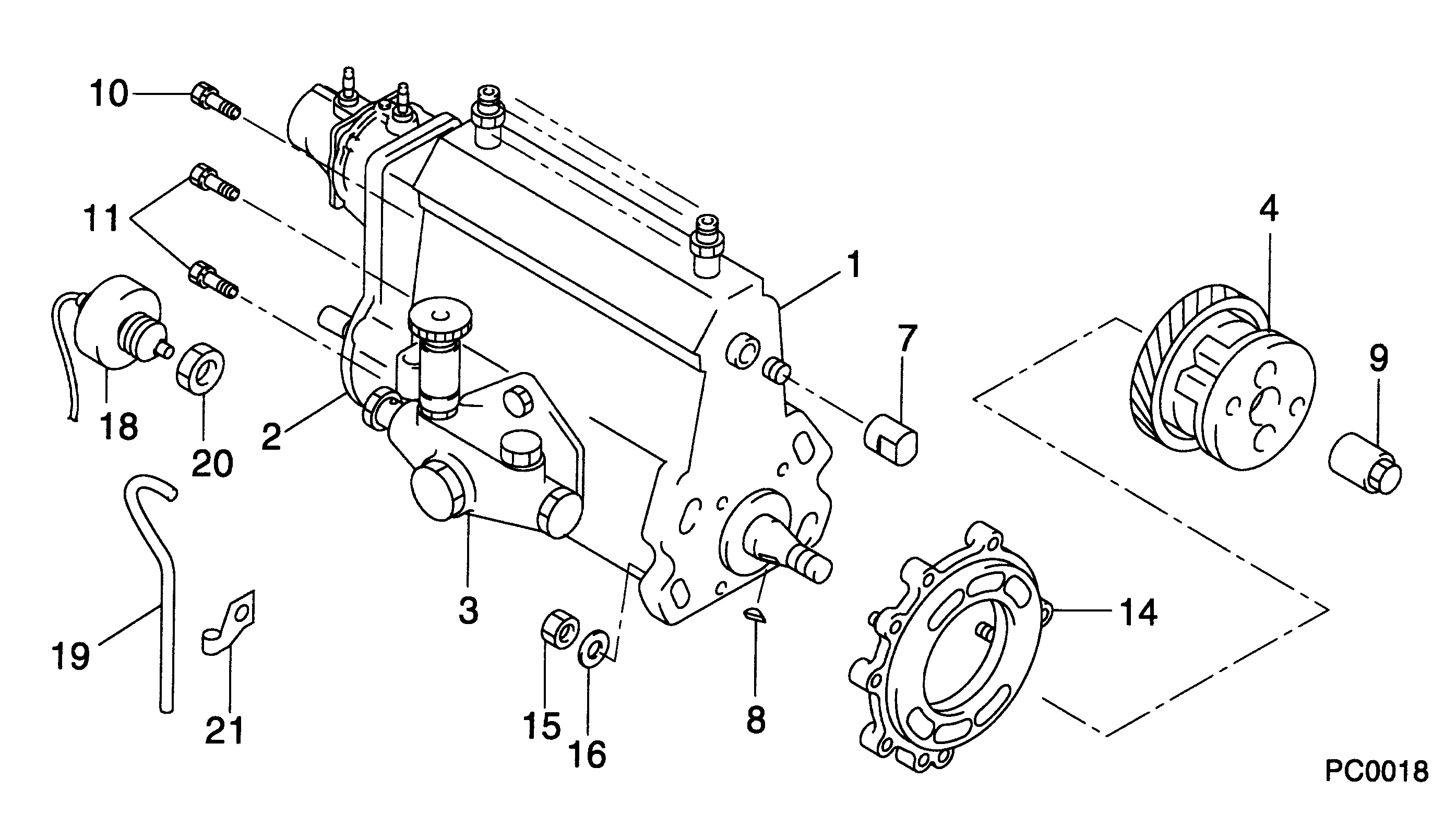
1. Remove nuts (1), cover (2), and the gasket. 2. Put No. 1 piston at the top center compression position (TC) with the following procedure:a. Remove plug (3), two bolts and cover (2) from the flywheel housing. b. Install Tool (B) in the flywheel housing. Use Tool (B) to slowly rotate the engine in the direction of normal rotation, (counterclockwise as seen from the flywheel end of the engine), until timing bolt (4) can be installed in the flywheel housing and into the hole in the flywheel. c. Remove the valve cover from the valve cover base. Check to see if both rocker arms (5) for the No. 1 cylinder can be moved backward and forward. The No. 1 piston is at the top center compression position (TC) when the timing bolt is installed in the flywheel and both rocker arms for the No. 1 cylinder can be moved backward and forward. If both rocker arms cannot be moved, the No. 1 piston is not at the top center compression position (TC). Remove the timing bolt from the flywheel and rotate the engine in the direction for normal rotation, (counterclockwise as seen from the flywheel end of the engine one full turn 360 degrees, and install the timing bolt again.3. Remove the timing bolt, and use Tool (B) to rotate the engine in the opposite direction of normal rotation (clockwise as seen from the flywheel end of the engine) a minimum of 30 degrees. The timing is correct if Tool (A) and the timing bolt can be installed at the same time. The timing procedure in the Testing & Adjustment Manual must be done again if the timing bolt and Tool (A) can not be installed at the same time.4. Remove the plug from the timing pin hole in the fuel injection pump housing. Install Tool (A) in the timing pin hole. 5. Remove eight bolts (6) and automatic timing advance (7). 6. Remove gear (9) from fuel injection pump camshaft (8).The following steps are for the installation procedure.7. Install gear (9) on fuel injection pump camshaft (8). 8. Install two 3/8 in 16 NC x 6 in (152.4 mm) long guide bolts (10). Space the guide bolts evenly.
There is a light spring located beneath the flyweight cover (12). Hold cover (12) while removing last nut (11). Slowly remove flyweight cover (12) to avoid dropping the spring.
9. Remove four nuts (11) and remove flyweight cover (12). 10. Put automatic timing advance (13) in position on the fuel injection pump camshaft, and install four bolts (14). Tighten bolts (14) just past finger tight. Remove guide bolts (15). 11. Install four nuts (16). Install Tool (C). 12. Tighten four knurled nuts (17) finger tight.
Do not use any tools to tighten the knurled nuts.
13. Install all mounting bolts (14) and tighten to 55 10 N m (41 7 lb ft).14. Loosen knurled nuts (17). Remove four nuts (16) and remove Tool (C).15. Install the spring and flyweight cover