Rating:
Information pump assy, injecti Denso
Product
Fuel Injection Pump
Vehicle engine
LAND CRUISER 2H
Engine
2H
Serial start-end
8007-
Info
Injector Nozzle
093500-1810
Injector nozzle:
0935001810
KIT List:
Part name
Kit1
Kit2
Components :
Scheme #.#:
№
Qty
Part num
Name
Remarks
Manufacture num
000
[01]
09300-00020
PUMP ASSY, INJECTI
A6,COMB
22010-06802
TOYOTA
Include in ##:
09300-00020
as PUMP ASSY, INJECTI
Cross reference number
Part num
Firm num
Firm
Name
09300-00020
22010-0680
PUMP ASSY, INJECTI
0930000020
22010-06802
TOYOTA
PUMP ASSY, INJECTI
Information:
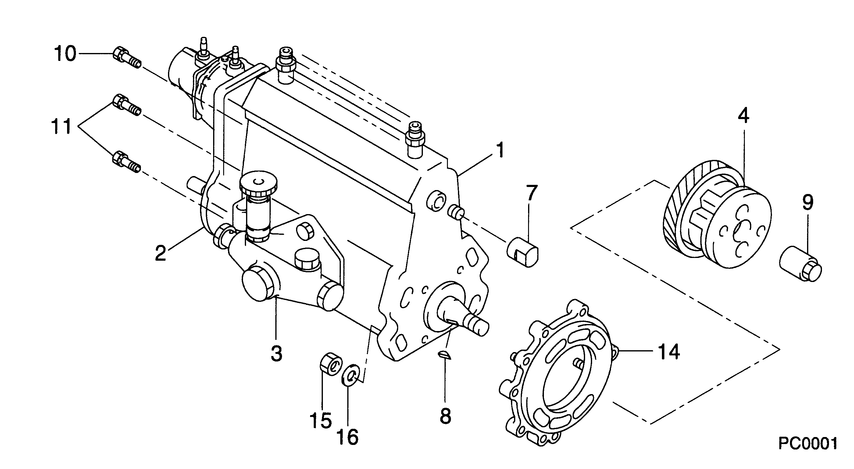
1. Remove plug (1) from the fuel injection pump housing.2. Use Tool (D) to loosen nut (2) for the fuel injection pump to be removed. Disconnect the fuel injection line nuts, and remove the felt washer. 3. Install Tool (A) in the fuel pump housing as shown with the square end down. Use a small amount of hand force to push down on Tool (A) while the control lever is moved forward to the "FUEL ON" position. Rack travel will stop in the center (zero) position. Hold a light forward force on the governor control lever to keep the fuel racks in the center (zero) position.4. Use Tool (B) to remove bushing (3) from the fuel injection pump housing. 5. Remove bushing (3) and O-ring seal (4).
When injection pumps, spacers and lifters are removed from the injection pump housing, keep the parts of each pump together so they can be installed in their original location.
6. Use Tool (C) to remove fuel injection pump (5). 7. Remove spacer (6) from the fuel injection pump housing. Make a note of the position from which each spacer was removed so each spacer can be installed in its original position.
Be careful when the fuel injection pumps are disassembled. Do not damage the surfaces of the plungers, barrels and bonnets. Any scratches will cause leakage inside the fuel injection pump. The plunger and barrel for each pump are made as a set. Do not put the plunger of one pump in the barrel of another pump. The check assemblies are made as a set. Do not mix the parts of the different check assemblies. Do not remove or make any adjustments of the gear segment on the plunger. It has been preset at the factory. If one part has wear, install a complete new pump assembly. Be careful when the plunger is put into the bore of the barrel.
8. Disassemble the fuel injection pump as follows: Remove ring (7). Separate bonnet (10) from barrel (9). Remove the spring and the check assembly from the bonnet. Remove plunger (8), the washer and spring from barrel (9).Install Fuel Injection Pumps
1. Inspect all parts for wear or damage. The plunger and barrel are serviced only as an assembly. 2. Put clean diesel fuel on plunger (1). Put plunger (1), washer (6) and spring (2) in position on barrel (3).3. Put check valve assembly (7) and spring (8) in bonnet (9). Connect bonnet (9) and barrel (3) together with ring (4). 4. Put spacer (10) into position in the pump housing bore. Be sure the correct spacer is with each pump. 5. Note the location of dowels (11) and (12) in the fuel injection pump housing. These dowels are for alignment of the fuel injection pump. 6. Slot (13) in gear segment (5) must align with dowel (11).7. Groove (14) must engage with dowel (12). 8. Use Tool (A) to put the fuel racks in the center (zero) position. See Remove Fuel Injection Pumps.9. Use Tool (E)