Rating:
Information pump assy, injecti Denso
Product
Fuel Injection Pump
Vehicle engine
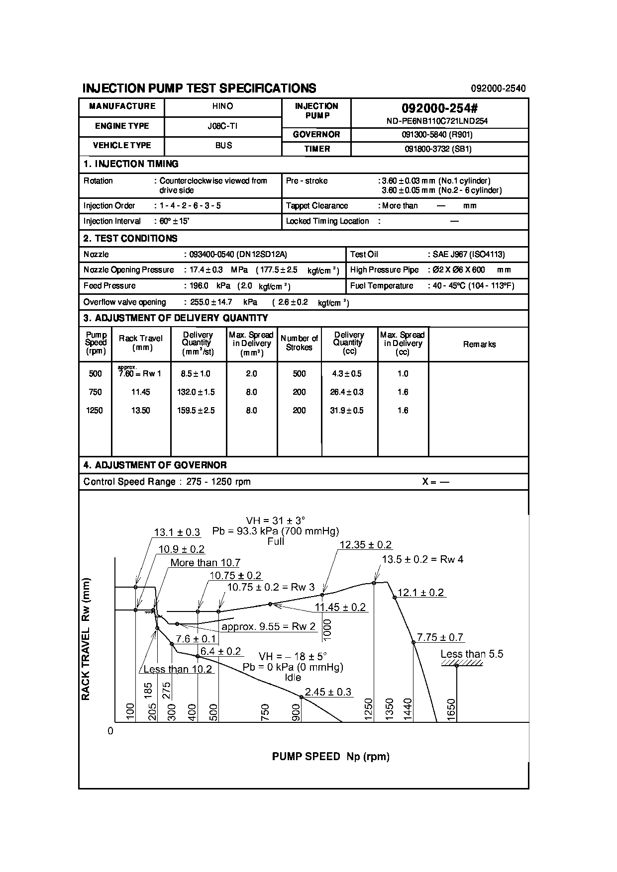
BUS J08C-TI
Engine
J08C-TI
Serial start-end
9610-
Info
Injector Nozzle
093500-6650
Injector nozzle:
0935006650
KIT List:
Part name
Kit1
Kit2
Cross reference number
Part num
Firm num
Firm
Name
0920002540
22010-7982
HINO
PUMP ASSY, INJECTI
0920002540
S2201-07982
HINO
PUMP ASSY, INJECTI
Information:
Start By:a. remove oil pump1. Check the main bearing caps for identification for their location and direction in the block. The caps must be installed in the same location and direction from which they were removed. 2. Remove number 2 through number 6 bearing caps (1). Remove thrust plates from the number 4 main bearing.
If the crankshaft is turned in the wrong direction, the tab of the bearing will be pushed between the crankshaft and cylinder block. This can cause damage to either the crankshaft or cylinder block or both.
3. Remove the upper halves of the main bearings by putting Tool (A) in oil hole (2) in the crankshaft. Turn the crankshaft in the direction which will push the end of the bearing with a tab out first.4. Remove the lower halves of the bearings from the caps. Install the bearings dry when the clearance checks are made. Put clean engine oil on the bearings for final assembly.5. Install the new bearings in the caps.6. Install the upper halves of the bearings in the cylinder with Tool (A).
Be sure tabs (3) on the back of the bearings fit in the tab slots of the caps and cylinder block. The serviceman must be very careful to use Plastigage, Tool (B) correctly. The following points must be remembered.
Make sure that the backs of the bearings and the bores are clean and dry.Make sure that the bearing locking tabs are properly seated in their slots.The crankshaft must be free of oil where the Plastigage touches it.If the main bearing clearances are checked with the engine upright or on its side, the crankshaft must be supported. Use a jack under an adjacent crankshaft counterweight and hold the crankshaft against the crown of the bearing. If the crankshaft is not supported, the weight of the crankshaft will cause incorrect readings.Put a piece of Plastigage on the crown of the bearing half that is in the cap. Do not allow the Plastigage to extend over the edge of the bearing.Install the bearing cap using the correct torque-turn specifications. Do not use an impact wrench. Be careful not to dislodge the bearing when the cap is installed.Do not turn the crankshaft with the Plastigage installed.Carefully remove the cap but do not remove the Plastigage. Measure the width of the Plastigage while it is in the bearing cap or on the crankshaft journal. Do this by using the correct scale on the package. Record the measurements.Remove the Plastigage before reinstalling the cap.When using Plastigage, the readings can sometimes be unclear. For example, all parts of the Plastigage are not the same width. Measure the major widths to make sure that they are within the specification range. Also, experience has shown that when checking clearances tighter than 0.10 mm (.004 in) the readings may be low by 0.013 to 0.025 mm (.0005 to .0010 in). Out-of-round journals can give faulty readings. Also, journal taper may be indicated when one end of the Plastigage is wider that the