Rating:
Information pump assy, injecti Denso
Product
Fuel Injection Pump
Vehicle engine
INDUSTRIAL 6BTA
Engine
6BTA
Serial start-end
9406-
Info
Injector Nozzle
KIT List:
Components :
Scheme #.#:
№
Qty
Part num
Name
Remarks
Manufacture num
000
[01]
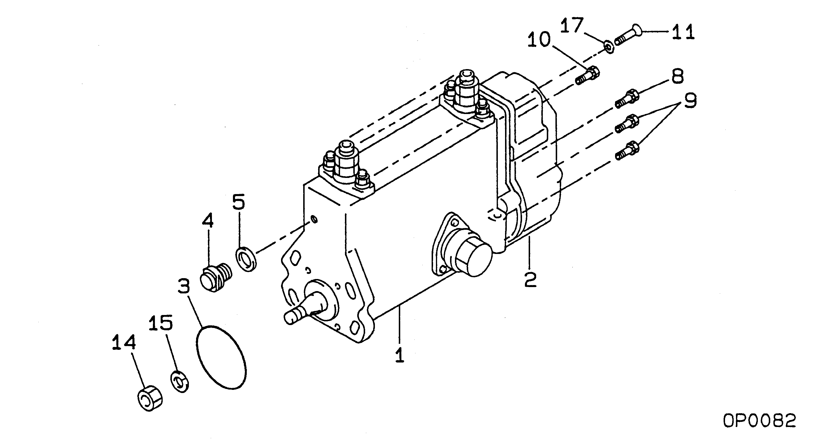
09200-00980
PUMP ASSY, INJECTI
NB6,RSVH
Include in ##:
09200-00980
as PUMP ASSY, INJECTI
Cross reference number
Part num
Firm num
Firm
Name
09200-00980
PUMP ASSY, INJECTI
Information:
2-12.2 Turn the crankshaft in the direction of engine rotation until the valves opposite the cylinder to be adjusted overlap.Fig. 2-1 and table below
2-2 Note for Refitment:The exhaust valve is left-hand as viewed from the exhaust air side.Fig. 2-2
2-33. Release locknut of adjusting screw and adjust rocker arm/valve stem clearance.Retighten locknut.Fig. 2-34. Recheck clearance and readjust if necessary.
2-45. Apply sealing compound to new gaskets for rocker chamber cover(s) and fit cover(s).Fig. 2-4 Checking The Compression Pressure
The specified pressure applies to min. 150/min starting speed of engine and 20°C reference temperature at sea-level. Prior to checking, run up engine briefly to medium speed, so the combustion chamber will be sufficiently sealed by an oil film. Perform check at zero delivery of injection pump.
2-51. Remove injector and in its place insert and secure adapter with seal.Fig. 2-5, left Attention:In the case of FL 912 W, remove heater plug and in its place insert adapter for compression pressure recorder.Fig. 2-5, right
2-62. Connect compression pressure gauge.Fig. 2-6
2-73. Take the compression pressure reading.Fig. 2-7
2-8 Important:Check that the individual compression pressures are within the range specified and about equal for all cylinders. Any deviations in pressure between cylinders should not exceed 15%.Fig. 2-8Determining TDC With Setting Device
1. Remove No. 1 rocker chamber cover.2. Turn crankshaft until valves overlap, then give crankshaft another half turn.
2-93. Mount setting device. Using pressure screw of device, press down one rocker arm through 5-6 mm.Fig. 2-9
2-104. Fit dial gauge with preload.Fig. 2-10
2-115. Secure graduated scale to V-belt pulley and fix pointer to dowel sleeve.Fig. 2-11 If engine is installed in vehicle, use graduated dial segment No. 100940.6. Set pointer to "O" on scale.7. Turn crankshaft carefully in nominal direction until piston pushes up the valve. Slowly turn farther until gauge pointer changes the direction. Set gauge at "O"8. Turn back crankshaft through about one revolution of gauge pointer, then again in original direction up to 0, 1 mm (10 graduations) from O-position. Read crankshaft position from scale and record.9. Turn crankshaft in running direction beyond "O" through about one revolution of the