Rating:
Information pump assy, injecti Denso
Product
Fuel Injection Pump
Vehicle engine
MARINE 6076A
Engine
6076A
Serial start-end
9311--9404
Info
Injector Nozzle
093500-5410
Injector nozzle:
0935005410
KIT List:
Part name
Kit1
Kit2
Components :
Scheme #.#:
№
Qty
Part num
Name
Remarks
Manufacture num
000
[01]
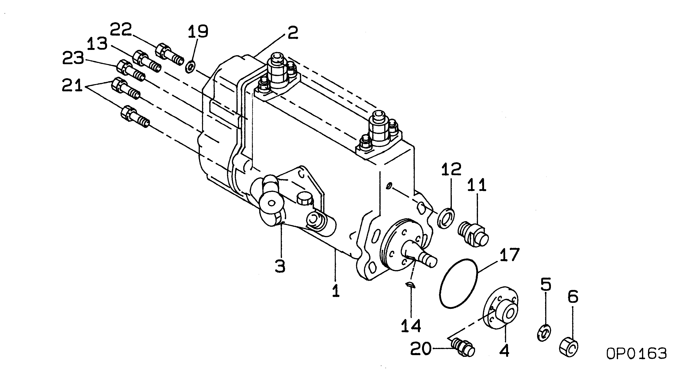
09200-00610
PUMP ASSY, INJECTI
NB6,RSVH
Include in ##:
09200-00610
as PUMP ASSY, INJECTI
Cross reference number
Part num
Firm num
Firm
Name
09200-00610
PUMP ASSY, INJECTI
Information:
Table 1
Revision Summary of Changes
01 Updated Illustration 1
02 Updated effectivity Introduction
The problem that is identified below does not have a known permanent solution. Until a permanent solution is known, use the solution that is identified below.Problem
Inadequate battery negative bonding to engine block causing incorrect diagnostic codes/tripping in the units that are disconnected from the engine-mounted charging alternator.Solution
Do not operate or work on this product unless you have read and understood the instruction and warnings in the relevant Operation and Maintenance Manuals and relevant service literature. Failure to follow the instructions or heed the warnings could result in injury or death. Proper care is your responsibility.
Illustration 1 g06575359
Generator set isolated DC supply system
(1) Electronic subsystem 1
(2) Electronic subsystem 2
(3) Electronic subsystem 3
(4) Generator set subsystem loads
(5) Engine ECM
(6) Starter
(7) Electronics power buss
(8) Electronics single point ground
(9) 12AWG (4 Sq.mm) bonding jumper (multi strand) wire
(10) Battery disconnect switch
(11) Customer ground connection
(12) Battery
(13) Battery charger
(14) Customer scopeNote: The red color connections in Illustration 1 are to be connected at customer site. Connections should be made after the battery disconnect switch (10).Caterpillar is aware of the problem, and is recommending the following interim solution.Install a 12AWG (4 Sq.mm) bonding jumper (multi strand) wire (9) connecting all electrical sensor grounding points (8) at the power distribution box to the customer ground connection (11). Refer to Illustration 1.Reference: Refer to Special Instruction, REHS4634, "Grounding Design Guide for Electric Power Generation Products".