Rating:
Information valve assy, suctio Denso
Compare Prices: .
As an associate, we earn commssions on qualifying purchases through the links below

QINGMO-AUTO FUEL PUMP PRESSURE REGULATOR OEM 294200-2760 2942002760
QINGMO-AUTO Thank you for visiting our store. Our brand, QINGMO-AUTO, provides you with high-quality service. || Please confirm before purchasing whether the image and number displayed on this link match your old item. If there is any inconsistency, please provide pictures, numbers or your VIN of the old parts for reference, in order to ensure that the product you purchased is fully functional. || This product is a professional automotive accessory. It is recommended to go to a professional repair shop for installation. || If you have any after-sales issues with this product, please contact QINGMO-AUTO, and we will provide you with answers and suggestions after sale. || Your package includes:1 PCS FUEL PUMP PRESSURE REGULATOR OEM 294200-2760 2942002760
QINGMO-AUTO Thank you for visiting our store. Our brand, QINGMO-AUTO, provides you with high-quality service. || Please confirm before purchasing whether the image and number displayed on this link match your old item. If there is any inconsistency, please provide pictures, numbers or your VIN of the old parts for reference, in order to ensure that the product you purchased is fully functional. || This product is a professional automotive accessory. It is recommended to go to a professional repair shop for installation. || If you have any after-sales issues with this product, please contact QINGMO-AUTO, and we will provide you with answers and suggestions after sale. || Your package includes:1 PCS FUEL PUMP PRESSURE REGULATOR OEM 294200-2760 2942002760

Parts Number 294200-2760 294009-0740 8 98145455-0 1460A056 1460A053 16700-5X00D A6860-LC10A 2942002760 2940090740 8 981454550 1460A056 1460A053 167005X00D A6860LC10A Control Valve Pack of 1 Piece
CAIJUN-AUTO PARTS NUMBER: 294200-2760 294009-0740 8 98145455-0 1460A056 1460A053 16700-5X00D A6860-LC10A 2942002760 2940090740 8 981454550 1460A056 1460A053 167005X00D A6860LC10A || You can send VIN to us if you are not sure about your OEM number || If you have any questions, please be free to contact us at any time || Durable materials with high performance || Enjoy your shopping from CAIJUN-AUTO
CAIJUN-AUTO PARTS NUMBER: 294200-2760 294009-0740 8 98145455-0 1460A056 1460A053 16700-5X00D A6860-LC10A 2942002760 2940090740 8 981454550 1460A056 1460A053 167005X00D A6860LC10A || You can send VIN to us if you are not sure about your OEM number || If you have any questions, please be free to contact us at any time || Durable materials with high performance || Enjoy your shopping from CAIJUN-AUTO

YANGM-AUTO 1pc/set OE# 294200-2760 294009-0740 8 98145455-0 1460A056 1460A053 16700-5X00D A6860-LC10A 2942002760 2940090740 8 981454550 1460A056 1460A053 167005X00D A6860LC10A control valve
YANGM-AUTO In oder to confirm the parts fitment, you may send VIN or parts number to us || OE# 294200-2760 294009-0740 8 98145455-0 1460A056 1460A053 16700-5X00D A6860-LC10A 2942002760 2940090740 8 981454550 1460A056 1460A053 167005X00D A6860LC10A || One Year Warranty
YANGM-AUTO In oder to confirm the parts fitment, you may send VIN or parts number to us || OE# 294200-2760 294009-0740 8 98145455-0 1460A056 1460A053 16700-5X00D A6860-LC10A 2942002760 2940090740 8 981454550 1460A056 1460A053 167005X00D A6860LC10A || One Year Warranty
You can buy:

Include in ##:
Number on scheme 033

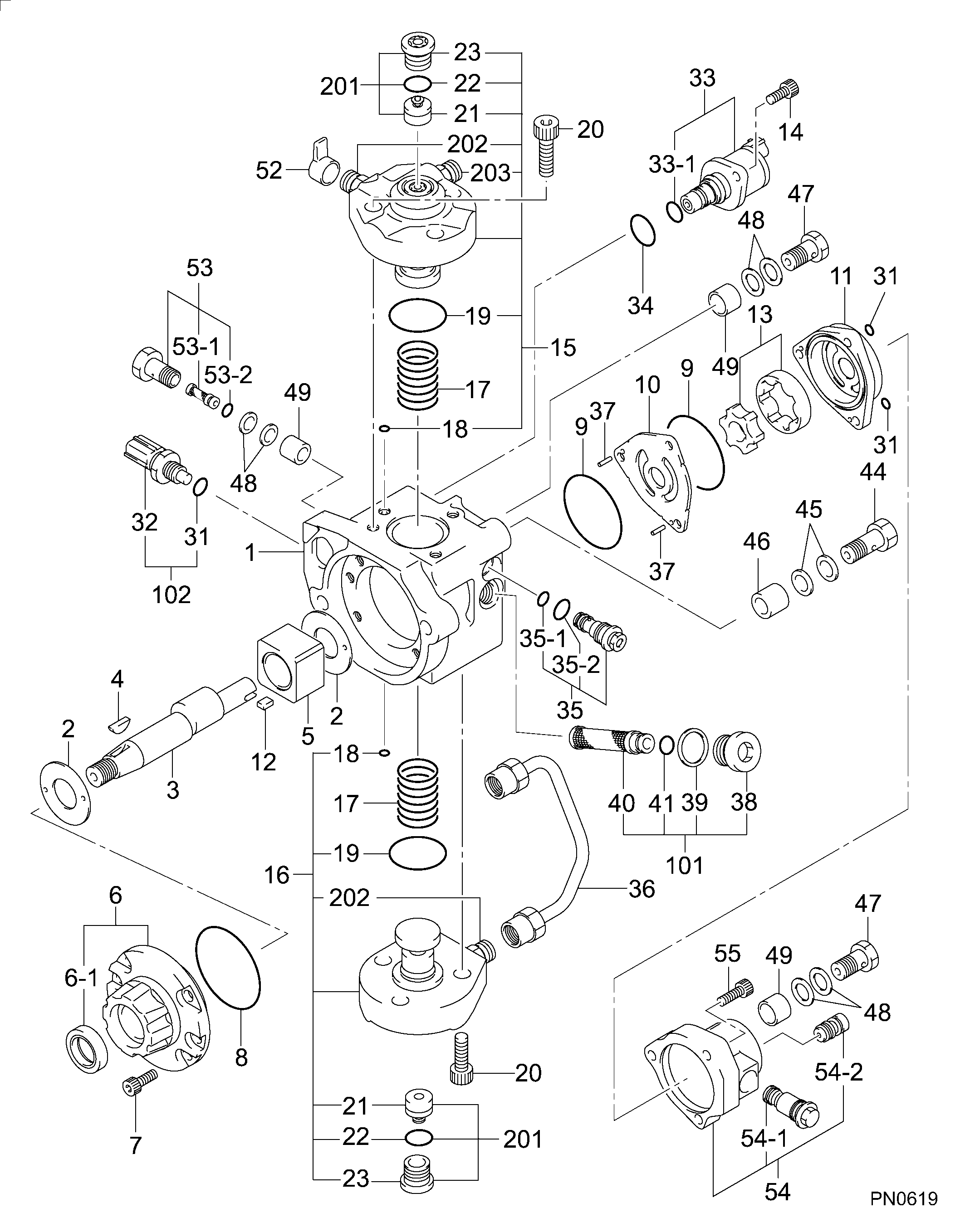
29400-01122
as VALVE ASSY, SUCTIO
Cross reference number
Part num
Firm num
Firm
Name
29420-02760
VALVE ASSY, SUCTIO
Information:
start by:a) remove turbocharger1. Make a mark on compressor housing (1), cartridge assembly (3) and turbine housing for correct installation. 2. Loosen clamp assemblies (2). Remove compressor housing (1) and cartridge assembly (3) from the turbine housing.3. Put the cartridge assembly in tooling (A).
When nut (5) is loosened, do not put a side force on the shaft.
4. Remove nut (5) and O-ring seal (6). 5. Put the cartridge assembly in a press. Remove the shaft assembly from compressor wheel (7) and cartridge (8). 6. Remove seal ring (10) and shroud (11) from shaft assembly (9).7. Use tooling (B) to remove snap ring (12).
Do not cause damage to insert (13) when it is removed.
8. Install screwdrivers as shown. Carefully lift insert (13) out of the cartridge assembly. 9. Remove sleeve (14) and O-ring seal (15) from the insert. 10. Remove two seal rings (16) from the sleeve.11. Remove deflector (17) from the cartridge assembly. 12. Remove ring (18). 13. Remove sleeve (19) from the cartridge assembly. Make an identification of the position of bearing (20) for assembly purposes.14. Remove bearing (20) from the cartridge assembly. 15. Remove ring (21). 16. Use tooling (C) to remove snap ring (23). Remove sleeve (22) and the lower snap ring. 17. Turn the cartridge housing over. Remove snap ring (26) with tooling (C).18. Remove bearing (25), sleeve (24) and the lower snap ring. Assemble Turbocharger (Schwitzer 4TF555)
Make sure all of the oil passages in the turbocharger cartridge housing are clean and free of dirt and foreign material. Put clean engine oil on all parts of the cartridge assembly. 1. Install snap ring (4) with tooling (A) in cartridge housing (1).2. Put sleeve (3) and bearing (2) in position. Install snap ring (5) with tooling (A).3. Turn the cartridge housing over. Install snap ring (8) with tooling (A). 4. Install sleeve (6) and snap ring (7).5. Put ring (10) in position in the cartridge housing. 6. Install bearing (9) with grooved side up. Make an alignment of the dowel in the housing with the hole on the right side of the notch.7. Put sleeve (12) in position. Install ring (11). 8. Put deflector (13) in position as shown. 9. Put two seal rings (15) in position on sleeve (14).10. Put O-ring seal (17) in position on insert (16). 11. Install sleeve (14) in insert (16).12. Install insert assembly (18) with the flange down in the cartridge housing. 13. Put O-ring seal (20) in position.14. Install snap ring (19) with tooling (B). 15. Put shaft assembly (22) in tooling (D). Put 6V2055 High Vacuum Grease in the groove for seal ring (23) at assembly to one half or more of the depth of the groove all the way around the groove. 16. Put seal ring (23) in position on the shaft assembly.17. Install shround (21) on the shaft assembly (22).18. Lightly oil the wheel face that will be under the nut. Put compressor wheel (24) in position.
Do not put a side force on the shaft