Rating:
Information valve assy, suctio Denso
Compare Prices: .
As an associate, we earn commssions on qualifying purchases through the links below

294200-2760 SCV Suction Valve Fuel Pump Suction Valve for Mitsubishi -
JKAPCYJFHF Condition:New|Non-Domestic Product:No|Other Part Number:2942002760 2942 0027 60|Number of Pieces:1|Custom Bundle:No| for MAN ufacturer Part Number:294200-2760|Superseded Part Number:294200-2760 294009-0740, for Mitsubishi L200 TRITON, for Isuzu for Holden D-MAX RODEO|Modified Item:No|Brand:Unbranded|Type:Fuel Pump Suction Valve|Interchange Part Number:294000-1372, 1460A053, 1460A056, 1460A056T| for MAN ufacturer :1 Year|Surface Finish:High quality|Country/Region of for MAN ufacture:China|UPC: || High-Quality Materials: Made from premium materials to ensure durability. || Perfect Fit: Precisely matched using OE numbers, ensuring seamless installation and perfect fit. || Superior Performance: Delivers exceptional performance enhancements in comfort, safety, and fuel efficiency. || Safety Assurance: Complies with strict industry standards , ensuring product safety and reliability.
JKAPCYJFHF Condition:New|Non-Domestic Product:No|Other Part Number:2942002760 2942 0027 60|Number of Pieces:1|Custom Bundle:No| for MAN ufacturer Part Number:294200-2760|Superseded Part Number:294200-2760 294009-0740, for Mitsubishi L200 TRITON, for Isuzu for Holden D-MAX RODEO|Modified Item:No|Brand:Unbranded|Type:Fuel Pump Suction Valve|Interchange Part Number:294000-1372, 1460A053, 1460A056, 1460A056T| for MAN ufacturer :1 Year|Surface Finish:High quality|Country/Region of for MAN ufacture:China|UPC: || High-Quality Materials: Made from premium materials to ensure durability. || Perfect Fit: Precisely matched using OE numbers, ensuring seamless installation and perfect fit. || Superior Performance: Delivers exceptional performance enhancements in comfort, safety, and fuel efficiency. || Safety Assurance: Complies with strict industry standards , ensuring product safety and reliability.

2942002760 Fuel Pump SCV Suction Control Valve for Mi&ts&ub&is&hi L200
2942002760 Fuel Pump SCV Suction Control Valve For Mi&ts&ub&is&hi L200 || UNIVERSAL COMPATIBILITY: Precision-engineered fuel pressure regulator valve designed to maintain optimal fuel pressure across various vehicle applications || DURABLE CONSTRUCTION: Heavy-duty metal construction with zinc-plated finish provides excellent corrosion resistance and long-lasting performance || EASY INSTALLATION: Features standard mounting points and connection ports for straightforward replacement of original equipment || PRECISE CONTROL: Advanced pressure regulation mechanism ensures consistent fuel delivery and optimal engine performance
2942002760 Fuel Pump SCV Suction Control Valve For Mi&ts&ub&is&hi L200 || UNIVERSAL COMPATIBILITY: Precision-engineered fuel pressure regulator valve designed to maintain optimal fuel pressure across various vehicle applications || DURABLE CONSTRUCTION: Heavy-duty metal construction with zinc-plated finish provides excellent corrosion resistance and long-lasting performance || EASY INSTALLATION: Features standard mounting points and connection ports for straightforward replacement of original equipment || PRECISE CONTROL: Advanced pressure regulation mechanism ensures consistent fuel delivery and optimal engine performance

You can buy:

Include in ##:
Number on scheme 033

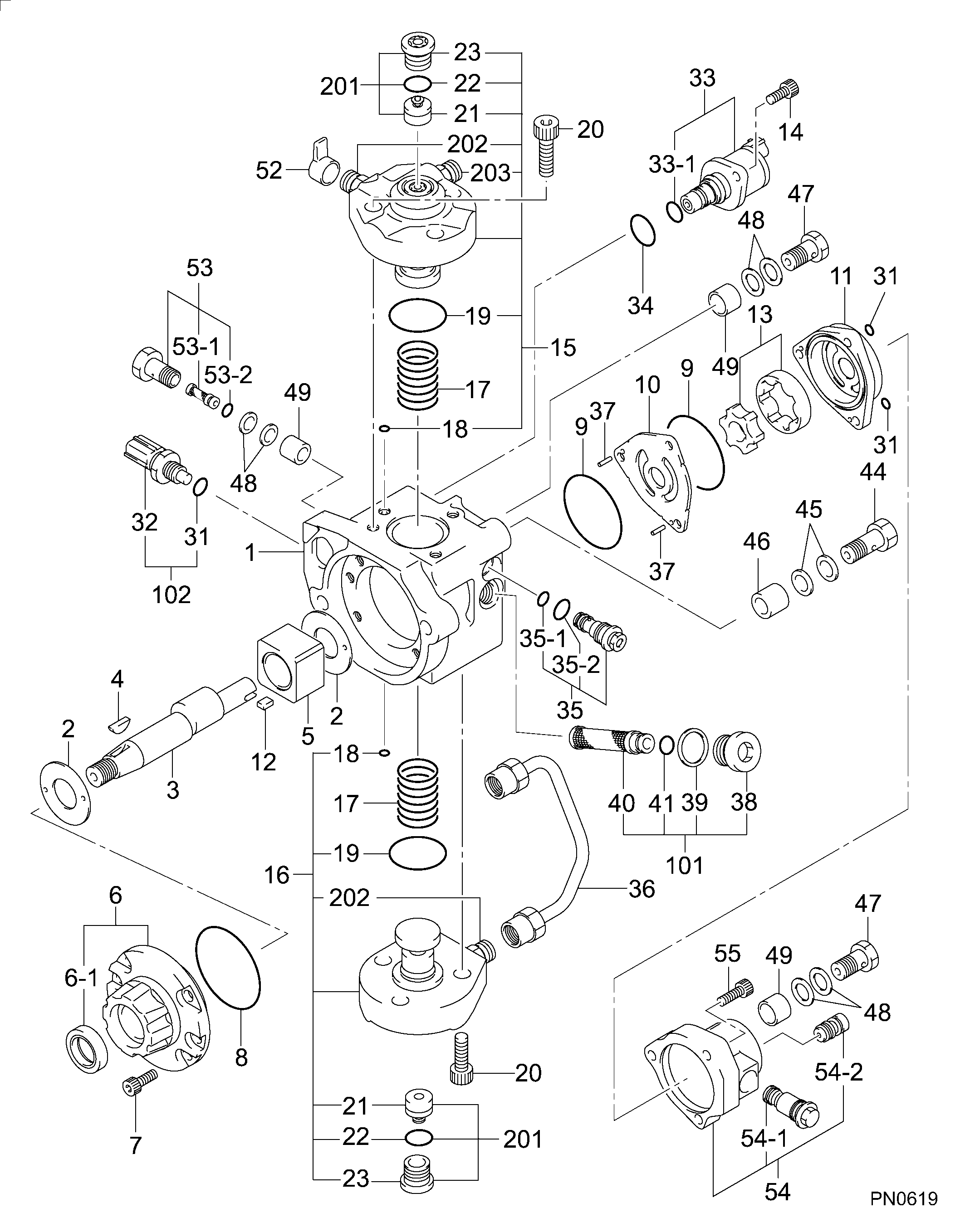
29400-01122
as VALVE ASSY, SUCTIO
Cross reference number
Part num
Firm num
Firm
Name
29420-02760
VALVE ASSY, SUCTIO
Information:
start by:a) remove turbocharger1. Make a mark on compressor housing (1), cartridge assembly (3) and turbine housing for correct installation. 2. Loosen clamp assemblies (2). Remove compressor housing (1) and cartridge assembly (3) from the turbine housing.3. Put the cartridge assembly in tooling (A).
When nut (5) is loosened, do not put a side force on the shaft.
4. Remove nut (5) and O-ring seal (6). 5. Put the cartridge assembly in a press. Remove the shaft assembly from compressor wheel (7) and cartridge (8). 6. Remove seal ring (10) and shroud (11) from shaft assembly (9).7. Use tooling (B) to remove snap ring (12).
Do not cause damage to insert (13) when it is removed.
8. Install screwdrivers as shown. Carefully lift insert (13) out of the cartridge assembly. 9. Remove sleeve (14) and O-ring seal (15) from the insert. 10. Remove two seal rings (16) from the sleeve.11. Remove deflector (17) from the cartridge assembly. 12. Remove ring (18). 13. Remove sleeve (19) from the cartridge assembly. Make an identification of the position of bearing (20) for assembly purposes.14. Remove bearing (20) from the cartridge assembly. 15. Remove ring (21). 16. Use tooling (C) to remove snap ring (23). Remove sleeve (22) and the lower snap ring. 17. Turn the cartridge housing over. Remove snap ring (26) with tooling (C).18. Remove bearing (25), sleeve (24) and the lower snap ring. Assemble Turbocharger (Schwitzer 4TF555)
Make sure all of the oil passages in the turbocharger cartridge housing are clean and free of dirt and foreign material. Put clean engine oil on all parts of the cartridge assembly. 1. Install snap ring (4) with tooling (A) in cartridge housing (1).2. Put sleeve (3) and bearing (2) in position. Install snap ring (5) with tooling (A).3. Turn the cartridge housing over. Install snap ring (8) with tooling (A). 4. Install sleeve (6) and snap ring (7).5. Put ring (10) in position in the cartridge housing. 6. Install bearing (9) with grooved side up. Make an alignment of the dowel in the housing with the hole on the right side of the notch.7. Put sleeve (12) in position. Install ring (11). 8. Put deflector (13) in position as shown. 9. Put two seal rings (15) in position on sleeve (14).10. Put O-ring seal (17) in position on insert (16). 11. Install sleeve (14) in insert (16).12. Install insert assembly (18) with the flange down in the cartridge housing. 13. Put O-ring seal (20) in position.14. Install snap ring (19) with tooling (B). 15. Put shaft assembly (22) in tooling (D). Put 6V2055 High Vacuum Grease in the groove for seal ring (23) at assembly to one half or more of the depth of the groove all the way around the groove. 16. Put seal ring (23) in position on the shaft assembly.17. Install shround (21) on the shaft assembly (22).18. Lightly oil the wheel face that will be under the nut. Put compressor wheel (24) in position.
Do not put a side force on the shaft