Rating:
Information valve assy, suctio Denso
Compare Prices: .
As an associate, we earn commssions on qualifying purchases through the links below

High Pressure Pump Suction Control Valve SCV 294200-0360 294200-0260 294200-0160 294200-0300 294200-0380 294200-0190 2942000170(294009-0260)
KONGLIE High pressure pump suction control valve for various applications || Compatible with SCV 294200-0360, 294200-0260, 294200-0160, 294200-0300, 294200-0380, 294200-0190, 2942000170 || Made with high-quality materials for durability and reliability || Easy to install and replace,Improves the performance and efficiency of the pump || High Pressure Pump Suction Control Valve SCV 294200-0360 294200-0260 294200-0160 294200-0300 294200-0380 294200-0190 2942000170
KONGLIE High pressure pump suction control valve for various applications || Compatible with SCV 294200-0360, 294200-0260, 294200-0160, 294200-0300, 294200-0380, 294200-0190, 2942000170 || Made with high-quality materials for durability and reliability || Easy to install and replace,Improves the performance and efficiency of the pump || High Pressure Pump Suction Control Valve SCV 294200-0360 294200-0260 294200-0160 294200-0300 294200-0380 294200-0190 2942000170

Manifold Pressure Intake MAP Sensor/Fit For 294200-0380 Fuel Pump Regulator Suction Control SCV Valve 294200-0360 294200-0300 294200-1110 294200-0460 MAP Pressure Sensor
XCSZWTY Features & Quality Manifold air pressure sensor has high reliability and stability, long in working life with temperature compensation, high level of accuracy. || Manufacturer Part Number : 9665523380, 96.655.233.80, 1920QK, 1920.QK V25110002 || OEM NO. : 294200-0380 || Material : Metal || Easy to install: You can replace parts by yourself, just need to remove the old parts, solve the vehicle problems by yourself, thus saving you a lot of money and time.
XCSZWTY Features & Quality Manifold air pressure sensor has high reliability and stability, long in working life with temperature compensation, high level of accuracy. || Manufacturer Part Number : 9665523380, 96.655.233.80, 1920QK, 1920.QK V25110002 || OEM NO. : 294200-0380 || Material : Metal || Easy to install: You can replace parts by yourself, just need to remove the old parts, solve the vehicle problems by yourself, thus saving you a lot of money and time.

You can buy:

Include in ##:
Number on scheme 033

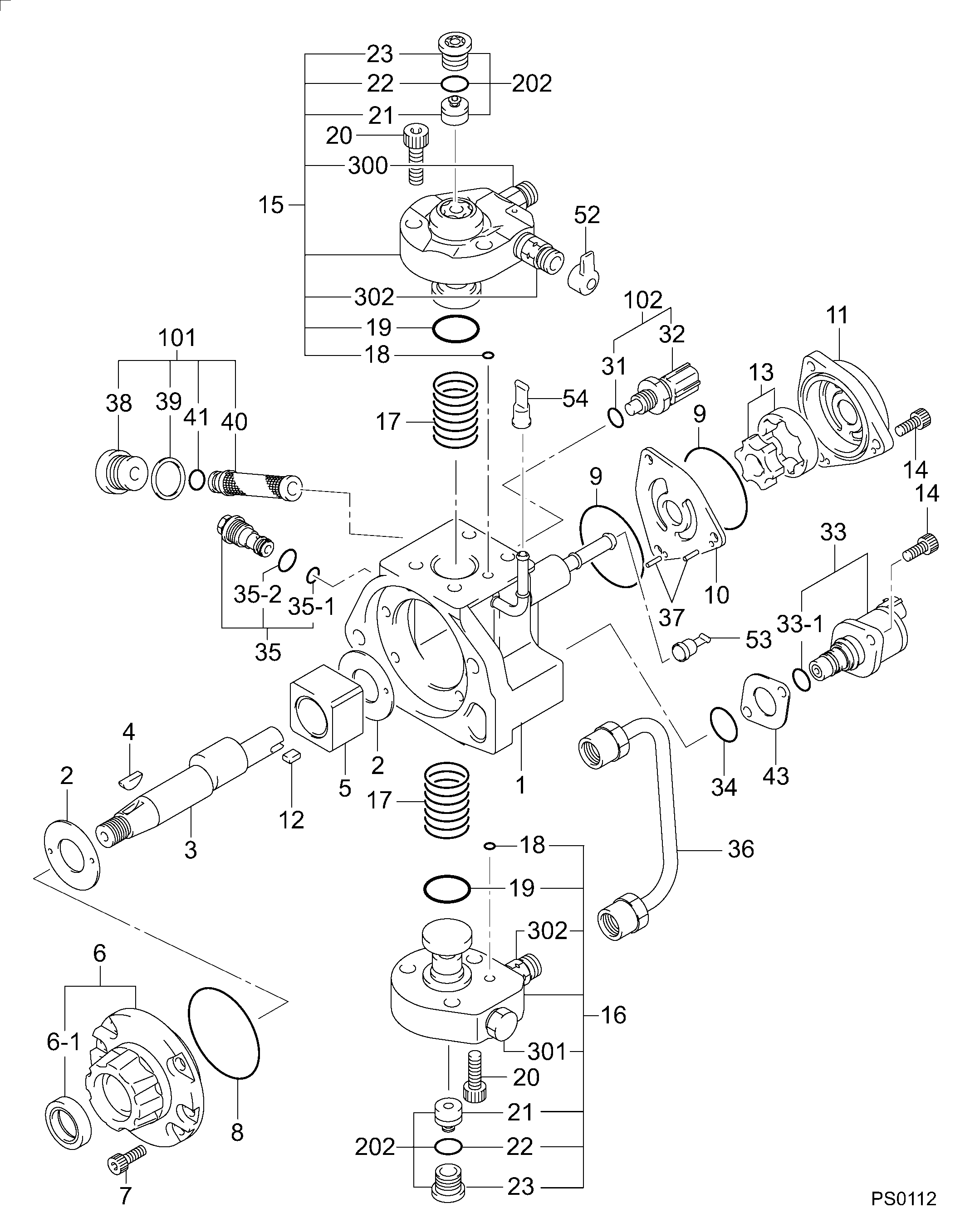
29400-00369
as VALVE ASSY, SUCTIO
Cross reference number
Part num
Firm num
Firm
Name
29420-00300
VALVE ASSY, SUCTIO
Information:
start by: a) remove fuel injection lines 1. Remove cover (1) from the front of the timing gear cover. Remove bolt (2) and washer (3). Install bolt (2) again to the position shown. Use tool (A) to loosen the pump drive gear from the camshaft. Remove tool (A) and bolt (2).2. Remove the governor linkage. Disconnect the fuel supply line. 3. Remove inlet oil tube (4) for the turbocharger.4. Disconnect the air tube from the fuel ratio control.5. Disconnect hose (5).6. Disconnect the three drain tubes from the fuel injection pump housing.7. Remove bracket (6).8. Remove the three nuts that hold the fuel injection pump housing and governor to the timing plate.9. Remove the fuel injection pump housing and governor.Install Fuel Injection Pump Housing And Governor
1. Use the following procedures to put the No. 1 piston at top center on the compression stroke. No. 1 piston at top center (TC) on the compression stroke is the starting point for all timing procedures. The engine is seen from the flywheel end when direction of flywheel rotation is given.a) Turn the flywheel approximately 30 degrees clockwise. The reason for making this step is to be sure the play is removed from the timing gears when the engine is put on top center. b) For engines with a timing pointer, remove the cover on the flywheel housing. Turn the flywheel counterclockwise until the "TC 1" mark on the flywheel is in alignment with the pointer.c) For engines with a timing bolt, turn the flywheel counterclockwise until a 3/8-16 NC bolt can be installed in the flywheel through the hole in the flywheel housing. Do not turn the flywheel backwards.d) Remove the breather from the valve cover. The rocker arms for No. 1 piston can be seen through the breather hole in the valve cover.e) Check to see if both rocker arms for the No. 1 piston can be moved backward and forward by hand. The No. 1 piston is at top center on the compression stroke when the "TC 1" mark on the flywheel is in alignment with the pointer, or the bolt can be put in the flywheel through the hole in the flywheel housing, and both rocker arms for the No. 1 piston can be moved backward and forward by hand. f) If both rocker arms can not be moved by hand, the No. 1 piston is not at top center on the compression stroke. Turn the flywheel counterclockwise one full turn (360°). For engines with a timing pointer, the "TC 1" mark on the flywheel must then be in alignment with the pointer. For engines with a timing bolt, the bolt must be installed in the flywheel through the hole in the flywheel housing.2. For engines with a timing pointer, turn the flywheel counterclockwise until the pointer is between the 1° and 2° mark on the flywheel as shown. 3. For engines with a timing bolt, do not turn the flywheel past this position. 4. Remove the
1. Use the following procedures to put the No. 1 piston at top center on the compression stroke. No. 1 piston at top center (TC) on the compression stroke is the starting point for all timing procedures. The engine is seen from the flywheel end when direction of flywheel rotation is given.a) Turn the flywheel approximately 30 degrees clockwise. The reason for making this step is to be sure the play is removed from the timing gears when the engine is put on top center. b) For engines with a timing pointer, remove the cover on the flywheel housing. Turn the flywheel counterclockwise until the "TC 1" mark on the flywheel is in alignment with the pointer.c) For engines with a timing bolt, turn the flywheel counterclockwise until a 3/8-16 NC bolt can be installed in the flywheel through the hole in the flywheel housing. Do not turn the flywheel backwards.d) Remove the breather from the valve cover. The rocker arms for No. 1 piston can be seen through the breather hole in the valve cover.e) Check to see if both rocker arms for the No. 1 piston can be moved backward and forward by hand. The No. 1 piston is at top center on the compression stroke when the "TC 1" mark on the flywheel is in alignment with the pointer, or the bolt can be put in the flywheel through the hole in the flywheel housing, and both rocker arms for the No. 1 piston can be moved backward and forward by hand. f) If both rocker arms can not be moved by hand, the No. 1 piston is not at top center on the compression stroke. Turn the flywheel counterclockwise one full turn (360°). For engines with a timing pointer, the "TC 1" mark on the flywheel must then be in alignment with the pointer. For engines with a timing bolt, the bolt must be installed in the flywheel through the hole in the flywheel housing.2. For engines with a timing pointer, turn the flywheel counterclockwise until the pointer is between the 1° and 2° mark on the flywheel as shown. 3. For engines with a timing bolt, do not turn the flywheel past this position. 4. Remove the