Rating:
Information valve assy, suctio Denso
Compare Prices: .
As an associate, we earn commssions on qualifying purchases through the links below


Original Fuel Metering unit Metering valve 0928400840 0928400008 294200-0360 294200-0300 294200-0260 294200-0160 294200-0170 - (Color: 294200-0160)
Generic Color: 294200-0160
Generic Color: 294200-0160

Manifold Pressure Intake MAP Sensor 294200-0170 Fuel Pump Regulator Suction Control Valve 2942000170 /Fit For Denso HP3 HP4 Mitsubishi 6M60T Hino Truck J08E MAP Pressure Sensor
XCSZWTY Features & Quality Manifold air pressure sensor has high reliability and stability, long in working life with temperature compensation, high level of accuracy. || OE NO.294200-0170 || Part NO.294200-0170 || /Fit For Denso HP3 HP4 Mitsubishi 6M60T Hino Truck J08E || Easy to install: You can replace parts by yourself, just need to remove the old parts, solve the vehicle problems by yourself, thus saving you a lot of money and time.
XCSZWTY Features & Quality Manifold air pressure sensor has high reliability and stability, long in working life with temperature compensation, high level of accuracy. || OE NO.294200-0170 || Part NO.294200-0170 || /Fit For Denso HP3 HP4 Mitsubishi 6M60T Hino Truck J08E || Easy to install: You can replace parts by yourself, just need to remove the old parts, solve the vehicle problems by yourself, thus saving you a lot of money and time.
You can buy:

Include in ##:
Number on scheme 031

29400-00294
as VALVE ASSY, SUCTIO
Cross reference number
Part num
Firm num
Firm
Name
29420-00170
VALVE ASSY, SUCTIO
Information:
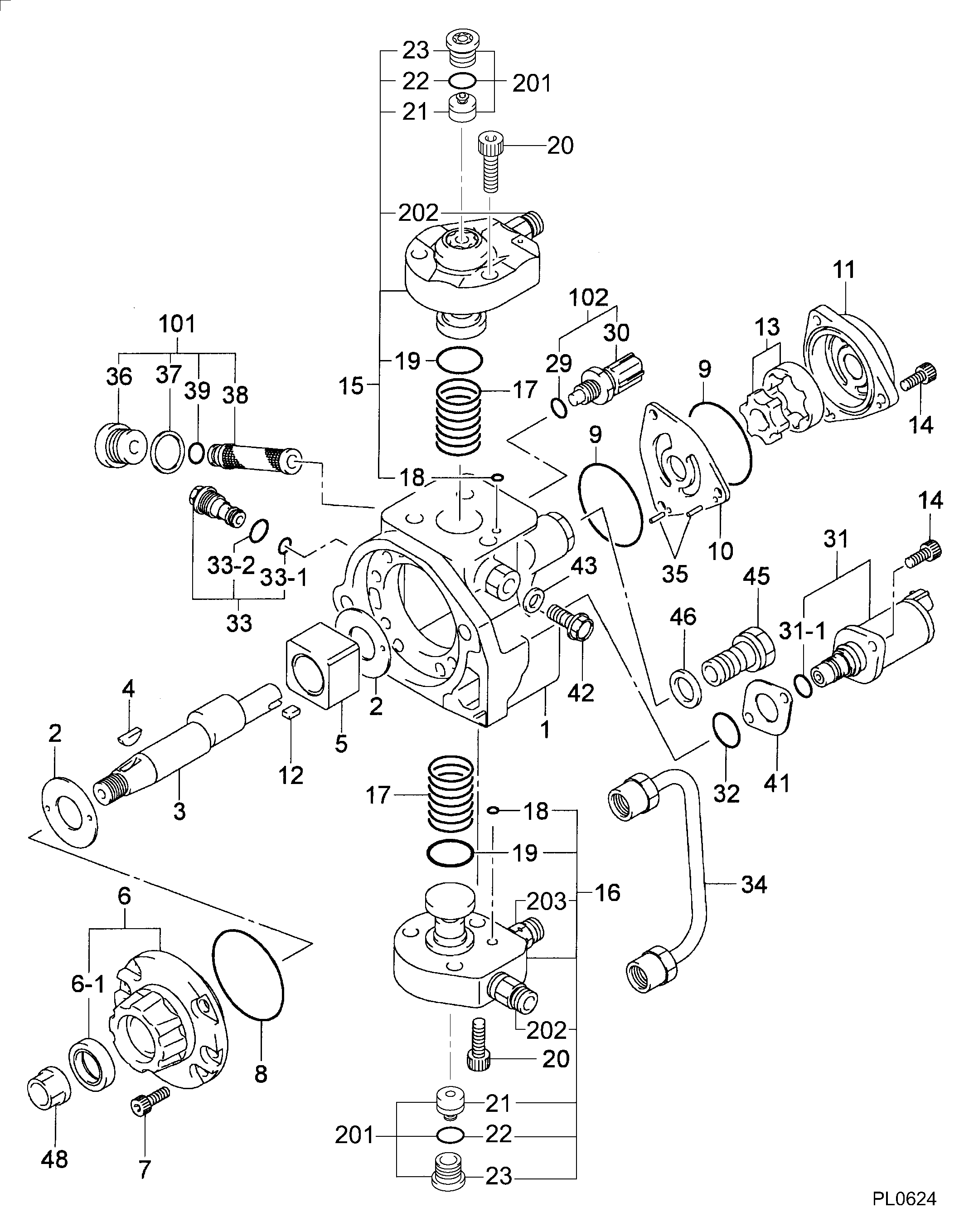
1. Remove strainer (2) from governor cover (1). 2. Bend the locks back and remove four bolts (6). Remove levers (4) and (5).3. Remove shaft (3) and the washer from the governor cover. 4. Remove two bearings (7) and two seals (8) from the governor cover with tooling (A). 5. Remove insulator (9) from governor cover (1). 6. Put a mark on the high idle screw (10) and make a note of each turn until the idle screw is removed from governor housing (13). This is done to get the approximate setting for assembly purposes. Remove the O-ring seal from the idle screw.
Do not mix the sequence of insulators, shims, spacers, contact, bar and spring. For more information see FUEL SETTING INFORMATION Fiche SBFY1106. The sequence of these parts can be different between engines. Bend lock (11) down and remove the two bolts. Remove torque spring group (12). Remove lock, retainer, insulator, spacer, contact, spring, spacer, shim, bar and insulator.
8. Bend the lock down and remove bolt (15) from control lever (14). Remove shaft (16) and control lever (14) from the governor housing. 9. Remove band assembly (17) from control lever (14).
Care must be taken when pin (18) is removed. The spring and plunger behind pin (18) are under spring force.
10. Remove pin (18), spring and plunger from control lever (14). 11. Remove bearings (19) and two seals (20) from governor housing (13). 12. Remove seat (21), spring washer (22), flat washer (24), spring washer (23) and spring (25). 13. Remove washer (27) from governor bolt (26).14. Remove ring (28) from seat (29). 15. Remove dowel (30) from seat (29). Remove seat (29) and governor bolt (26) as a unit. Remove bolt (26) from seat (29). 16. Remove washer (31), spring (32), washer (33) and sleeve (34) from the servo piston valve. 17. Remove ring (38), large race (37), bearing (35) and small race (36) from sleeve (34). 18. Remove lock (40) from flyweight assembly (39). Remove flyweight assembly (40). 19. Bend the locks from bolts (41) and remove bolts (41).20. Remove bracket (42) and the servo piston assembly as a unit. 21. Remove piston (44) from pin (43). Remove pin (43) from bracket (42). 22. Remove sleeve (45) and valve (46) from piston (44). Remove O-ring seal (47) from sleeve (45). 23. Remove shaft (48) from bracket (42) with a hammer and punch.24. Remove lever (49) from bracket (42). 25. Hit (tap) lightly on cylinder (50) to remove it from the governor plate. 26. Remove O-ring seals (51) from cylinder (50). 27. Remove spiral ring (53), and then remove dowel (52) behind the spiral ring. 28. Remove drive assembly (54) and stop (55) from drive gear (56). 29. Turn the governor plate over and remove snap ring (57) from drive gear (56) with tool (B).30. Remove drive gear (56) from the governor plate. 31. If a replacement is needed, remove dowels (59), (60) and (61).32. Remove bearing (58) from the governor plate with tooling (A).Assemble Governor
1. If