Rating:
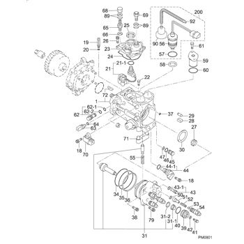
Information valve sub-assy, de Denso
Include in ##:
09800-00300
as VALVE SUB-ASSY, DE
Cross reference number
Part num
Firm num
Firm
Name
09845-00070
VALVE SUB-ASSY, DE
Information:
1. Disconnect air lines (2) and (3) from the air compressor.2. Disconnect water line (1) and oil line (4) from the air compressor. 3. Remove three nuts (5) and washers that hold the air compressor to the accessory drive.4. Remove air compressor (6).Install Air Compressor
1. Put oil in the bore of the accessory drive. Put air compressor (1) in position on the accessory drive. Install the washers and nuts that hold it in place. 2. Connect oil line (5) to the air compressor.3. Connect air lines (3) and (4) to the air compressor.4. Connect water line (2) to the air compressor.end by:a) install air compressor governorDisassemble Air Compressor
start by:a) remove air compressor 1. Remove elbow (1) and adapter. Remove the gasket, screen and gasket from behind the flange.2. Remove air compressor governor (2).3. Put a mark on the head assembly and block for correct assembly. 4. Remove six bolts (3). Remove head assembly (4). 5. Remove inlet valve springs (5) from the head assembly.6. Remove discharge valve seats (6). 7. Remove discharge valves (7). Remove springs from behind the valves. Check the discharge valve stops for wear or damage. If the discharge valve travel exceeds .057 in. (1.45 mm), make a replacement of the head assembly. 8. Remove inlet valves (8) from guides. Remove guides (9) from around the inlet valve seats. 9. Remove unloader spring (10), spring seat and spring saddle (12).10. Remove unloader plungers (11) and guides. 11. To remove unloader pistons (13) from the bore, put a cover over the inlet port, then blow air pressure in the governor mounting pad unloader port (14). 12. Check inlet valve seats (15) and unloader bore bushings (16)
