Rating:
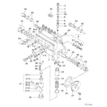
Information valve assy, overfl Denso
Include in ##:
09010-03322
as VALVE ASSY, OVERFL
Cross reference number
Part num
Firm num
Firm
Name
09031-00110
ME702087
VALVE ASSY, OVERFL
0903100110
ME702087
MITSUBISHI
VALVE ASSY, OVERFL
Information:
Introduction
There are two types of fuel injection control linkages that are used on these engines.
The current designs of the fuel injection control linkages are the 162-8756 Fuel Injection Control Linkage (used for 3116 engines and 3126 engines) and the 170-7670 Fuel Injection Control Linkage (used for 3114 engines). If you have a 162-8756 Fuel Injection Control Linkage or a 170-7670 Fuel Injection Control Linkage this publication is not applicable to your engine.
The former designs of the fuel injection control linkages are the 102-7459 Fuel Injection Control Linkage (for 3116 and 3126 engines), and the 4P-9048 Fuel Injection Control Linkage (for 3114 engines).These fuel injection control linkages may be inspected and modified, if desired. Refer to Illustration 4.
You may perform the "Inspection Procedure" in order to determine the type of fuel injection control linkage on your engine. Refer to Illustration 4 for visual identification of the current 162-8756 Fuel Injection Control Linkage or the current 170-7670 Fuel Injection Control Linkage .This publication explains the inspection of the former 102-7459 Fuel Injection Control Linkage and the former 4P-9048 Fuel Injection Control Linkage . This publication also contains the procedures for the modification of the former 102-7459 Fuel Injection Control Linkage and the former 4P-9048 Fuel Injection Control Linkage . The former fuel injection control linkages may be modified by the installation of the 180-7956 Clamp Assembly Kit and the 180-7957 Bushing Assembly Kit , if desired. This modification does not apply to the current 170-7670 Fuel Injection Control Linkage or the current 162-8756 Fuel Injection Control Linkage .Suggested Tools and Parts
Table 1
Suggested Tools
Tool Part Number Part Description Qty
A 1U-6675 Spring Compressor (1) 1
B 8T-4177 Bolt (1) 1
C 128-8823 Pliers (1) (2) 1
D 136-4149 Governor Pliers (3) 1
E - Rotary File (4) 1
( 1 ) Part of the 128-8822 Governor Tool Group
( 2 ) Earlier 128-8823 Pliers are 150 mm (6 inch) long. Newer 128-8823 Pliers are 238 mm (9.4 inch) long. If the 128-8823 Pliers are 238 mm (9.4 inch) long, use the 136-4149 Governor Pliers (D).
( 3 ) The 136-4149 Governor Pliers must be slightly modified.
( 4 ) The rotary file is used for the modification of the fuel injection control linkage.
Illustration 1 g00701990
136-4149 Governor Pliers (D) The 136-4149 Governor Pliers must be modified slightly. The governor pliers have jaws that are covered with rubber. The rubber coating should be removed on the last 10 mm (0.04 inch) of the tips in order to expose the original metal teeth. Refer to Illustration 1. This modification will not affect the original function of the pliers.The following parts that are listed in Table 2 may be used in order to install the 180-7956 Clamp Assembly Kit
