Rating:
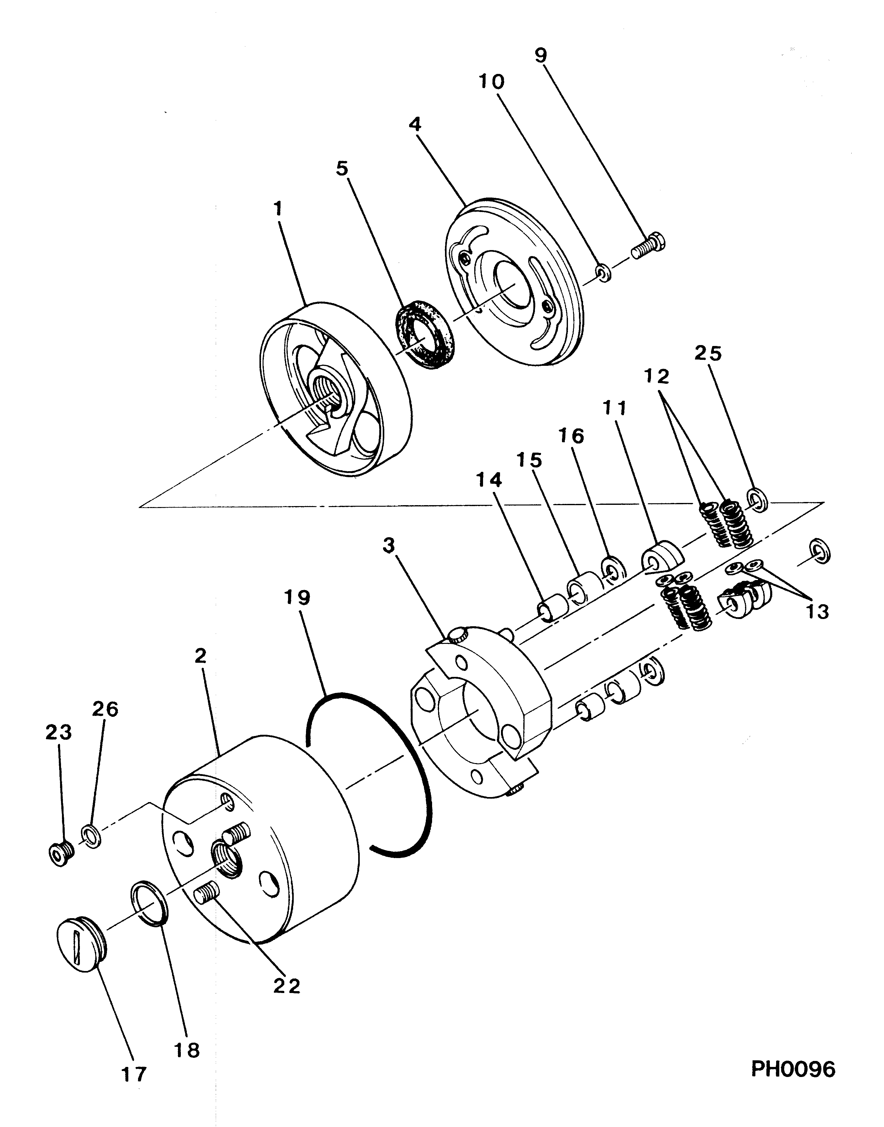
Information timer assy, automa Denso
Scheme #.#:
№
Qty
Part num
Name
Remarks
Manufacture num
000
[01]
09180-01801
TIMER ASSY, AUTOMA
*1
9310-
22510-1650
HINO
Include in ##:
09180-01801
as TIMER ASSY, AUTOMA
Cross reference number
Part num
Firm num
Firm
Name
09180-01801
22510-1650
TIMER ASSY, AUTOMA
Information:
Start By:a. remove cylinder head assemblyb. remove oil panc. remove piston cooling jets 1. Remove two rod cap bolts (1) from each rod. Remove rod caps (2).2. Using a soft jawed hammer, tap rod (3) away from the crankshaft. Remove bearing half (4).
When removing the cylinder pack, watch the rod, and prevent it from catching on the bore in the cylinder block as it comes out.
3. Install tooling (A), and remove cylinder pack (5). 4. Remove cylinder liner seal (6) at the base of the spacer block.5. Remove the remainder of tooling (A) from cylinder pack (5). 6. Remove the rod and piston from the cylinder liner. Remove seal (7) from the cylinder liner. The following steps are for the installation of the cylinder pack.7. Install a new cylinder liner seal (6) in the base of the spacer block. Lubricate the seal with clean engine oil. Some engines use pistons which have the word "FRONT" stamped on the crown of the piston. Be sure the word "FRONT" is toward the front of the engine when the piston is installed. The etched number on the connecting rod must be on the right side and must be installed in the corresponding cylinder. 9U-5839 Liquid Gasket Material is applied to the cylinder liners in the area shown in the illustration. The liquid gasket material helps prevent oil leaks from between the cylinder block and spacer block. DO NOT apply any 9U-5839 Liquid Gasket Material between the engine spacer block and the cylinder block surfaces. Using excessive amounts of liquid gasket material on the liner flange seat can cause oil leaks due to distortion of the O-ring seals between the spacer block and cylinder block.8. Install a new seal (7) on the cylinder liner.9. Lubricate the lower portion of the cylinder liner with clean engine oil. Be sure the corresponding crankshaft throw is at bottom center. Position cylinder pack (5), and guide rod (3) into place. Use tooling (B), and press cylinder pack (5) into place. Refer to the "Systems Operation Testing And Adjusting" module, Form No. SENR5561, for checking Cylinder Liner Projection.10. With rod (3) in this position, install the upper half of rod bearing (4). Be sure the bearing tab properly engages with the slot in the connecting rod. Lubricate the bearing surface with clean engine oil. Tap the piston down with a soft faced hammer until the rod and bearing contacts the crankshaft.11. With rod cap bearing in place and lubricated, install rod cap (2). Lubricate rod bolts (1) with 2P2506 Thread Lubricant. Install rod bolts (1), and tighten them to a torque of 130 7 N m (95 5 lb ft). Mark each bolt head, and tighten each bolt an additional 1/6 60 5 ( turn).End By:a. install piston cooling jetsb. install oil panc. install cylinder head assembly