Rating:
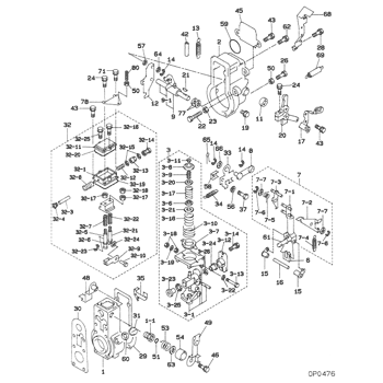
Information shim Denso
Include in ##:
09130-00513
as SHIM
Cross reference number
Part num
Firm num
Firm
Name
09133-10150
SHIM
0913310150
22885-2490A
HINO
SHIM
0913310150
22713-58234
TOYOTA
SHIM
0913310150
ME703154
MITSUBISHI
SHIM
0913310150
S2288-52490-A
HINO
SHIM
Information:
Illustration 13 g01882428
(2) 319-8937 Clamp As (7) 132-7467 Bracket (11) 3B-4508 Lockwasher (20) 8T-4223 Hard Washer (21) 8T-4244 Nut (22) 8T-4910 Bolt
Place two 319-8937 Clamp As (2) onto support assembly (3) and install by using four 8T-4223 Hard Washers (20), four 3B-4508 Lockwashers (11), four 8T-4910 Bolts (22) and four 8T-4244 Nuts (21). Install 132-7467 Bracket (7) on one of the clamp assemblies (2) that sits on the filter module of the diesel particulate filter. Refer to Illustration 13.
Illustration 14 g01882433
(a) Outlet module tube (6) 255-2899 Tail Pipe As (13) 7S-8735 Clamp (16) 8T-4133 Nut (18) 8T-4186 Bolt
Install 255-2899 Tail Pipe As (6) on outlet module tube (a) of the diesel particulate filter by using 7S-8735 Clamp (13), one 8T-4186 Bolt (18) and one 8T-4133 Nut (16). Refer to Illustration 14.
Illustration 15 g01882455
(b) Inlet module tube (4) 319-8946 Tube As (8) 094-7583 Clamp As
Connect 319-8946 Tube As (4) to inlet module tube (b) of the diesel particulate filter by using 094-7583 Clamp As (8). Refer to Illustration 15.
Illustration 16 g01882458
(9) 2S-7010 Clip (15) 8T-4121 Hard Washer (16) 8T-4133 Nut (19) 8T-4195 Bolt
Connect 2S-7010 Clip (9) to bracket (7) by using two 8T-4121 Hard Washers (15), one 8T-4195 Bolt (19) and one 8T-4133 Nut (16). Refer to Illustration 16.
Illustration 17 g01882777
(10) 1R-6484 Nut (12) 5I-7679 Gasket
Connect the other end of tube assembly (4) to the turbo by using one 5I-7679 Gasket (12) and six 1R-6484 Nuts (10). Refer to Illustration 17.
Illustration 18 g01882779
(5) 341-3341 Sheet As
Modify 341-3341 Sheet As (5) (rear panel) to provide a shield between the diesel particulate filter group and the hydraulic hoses in the event of a hydraulic hose rupture. A portion of sheet assembly (5) needs to be extended in order to accommodate the diesel particulate filter group. Refer to Illustration 18.
Illustration 19 g01905115
Illustration 20 g01905117
Illustration 21 g01905134
Install 341-3341 Sheet As (5) near the inlet module of the diesel particulate filter. Refer to Illustration 18.In order to avoid interference with diesel particulate filter group (1) and sheet assembly (5), the case drain line will need to be rotated, and two fittings will need to be switched.
Illustration 22 g01904186
Rear View (c) Case drain line (d) Connector assembly (e) Elbow assembly (f) Hydraulic tank (g) Case drain oil filter
Remove case
