Rating:
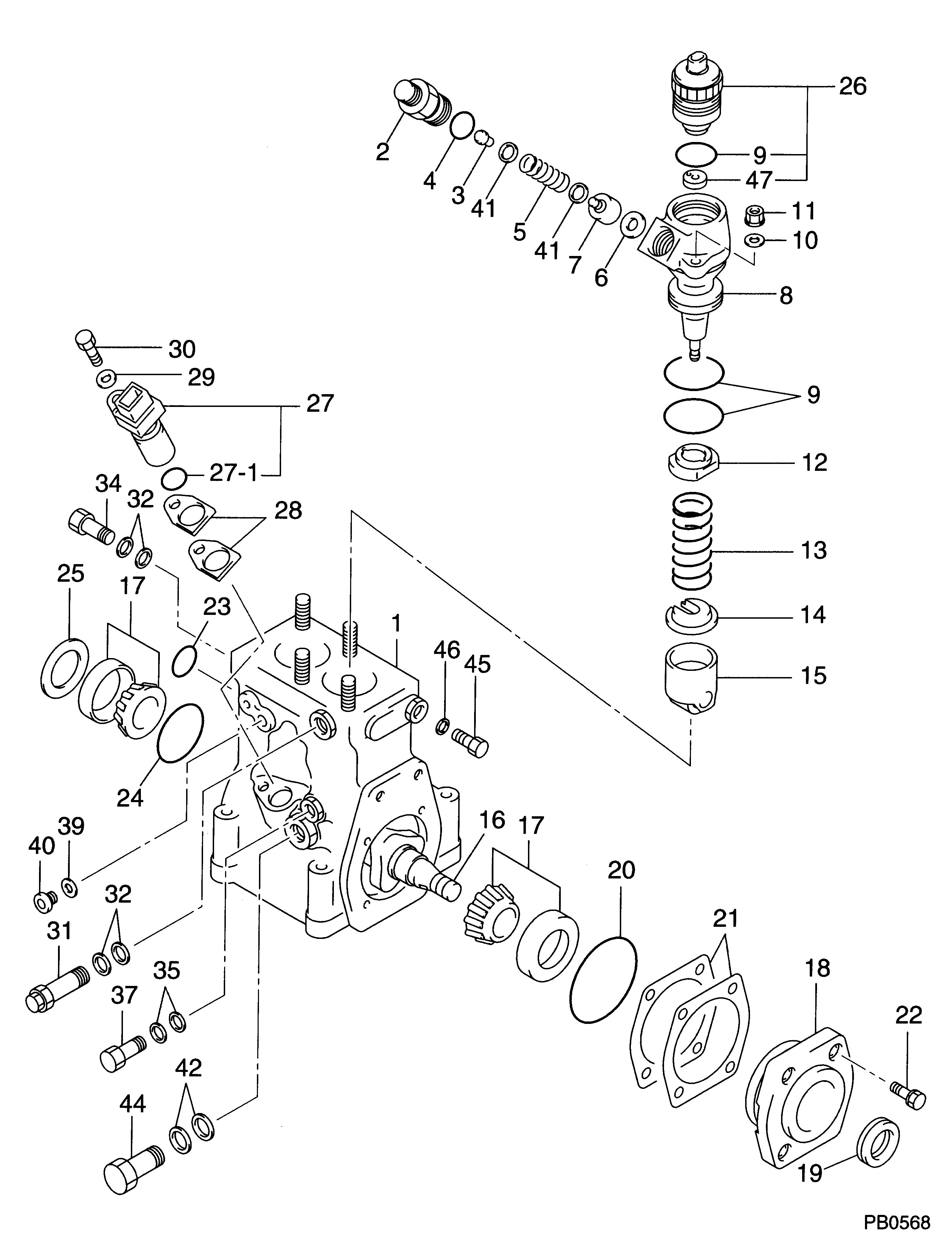
Information sensor assy, crank Denso
Compare Prices: .
As an associate, we earn commssions on qualifying purchases through the links below

029600-0580 Crankshaft Position Sensor Compatible with Komatsu PC450-7 Excavator J08C J05C Excavator Parts
Generic 029600-0580 Crankshaft Position Sensor Compatible with Komatsu PC450-7 Excavator J08C J05C Excavator Parts
Generic 029600-0580 Crankshaft Position Sensor Compatible with Komatsu PC450-7 Excavator J08C J05C Excavator Parts

Dormcoo 029600-0580 Camshaft Speed Sensor 6217-81-9210 Replacement for Kobelco SK200 SK210 Hino Engine J05 J08
Dormcoo Replace Part Number: 029600-0580 6217-81-9210 || Vehicle Sub Model Engine: Compatible with Kobelco SK200 SK210 Hino engine J05 J08 || Package included: 1* Camshaft Position Sensor || Type: Camshaft Position Sensor || Please check part photos, part number (OE# of your old part), part description and compatibility chart above carefully and compare them with your old part to make sure it is what you need.
Dormcoo Replace Part Number: 029600-0580 6217-81-9210 || Vehicle Sub Model Engine: Compatible with Kobelco SK200 SK210 Hino engine J05 J08 || Package included: 1* Camshaft Position Sensor || Type: Camshaft Position Sensor || Please check part photos, part number (OE# of your old part), part description and compatibility chart above carefully and compare them with your old part to make sure it is what you need.

Engine Speed Sensor Revolution Crankshaft Camshaft Position 6217-81-9210 029600-0580 Compatible with PC400-7 PC450-8 PC200-5 Excavator Parts Machinery Parts (A)
Generic Engine Speed Sensor Revolution Crankshaft Camshaft Position 6217-81-9210 029600-0580 Compatible with PC400-7 PC450-8 PC200-5 Excavator Parts Machinery Parts || Place of Origin:Guangdong, China
Generic Engine Speed Sensor Revolution Crankshaft Camshaft Position 6217-81-9210 029600-0580 Compatible with PC400-7 PC450-8 PC200-5 Excavator Parts Machinery Parts || Place of Origin:Guangdong, China
Include in ##:
Cross reference number
Part num
Firm num
Firm
Name
02960-00580
SENSOR ASSY, CRANK
Information:
Problem
The fuel lines on certain D10N Tractors; 651E And 657E Tractors; 772B Tractors; 773B Trucks; and 992C Loaders may fail. New fuel line groups can be installed that have a longer service life.
Affected Product
Model & Identification Number
Group 1
D10N (2YD442-1937, 2YD1939, 2YD1942)
651E (89Z170-172, 89Z174-187, 89Z189-270)
657E (90Z183-206; 91Z310-434)
772B (64W178-183)
773B (63W2172, 63W2173, 63W2175, 63W2177-3417, 63W3419; 5SC1-140)
992C (49Z1120-1878)
Group 2
D10N (2YD1938, 2YD1940-1941, 2YD1943-2230)
657E (90Z207-208; 91Z435-460)
772B (64W184-208)
773B (63W3418, 63W3420-3686)
992C (49Z1879-2015)
Group 3
D10N (2YD2231-2406)
657E (90Z209-220)
773B (63W3687-3940)
992C (49Z2016-2125)
Parts Needed
Group 1
1 - 7C6589 Clamp 2 - 7C6591 Clamp 2 - 7C7747 Clamp 1 - 7E3539 Lines Group 1 - 6I0347 Bracket Assembly 1 - 6I0361 Lines Group 6 - 9N3388 Screw-Lock2 - 4P3677 Clamp2 - 4P3678 Clamp8 - 5P4939 Screw A2 - 0L2070 Bolt5 - 0S1590 Bolt3 - 8T1296 Washer2 - 9Y3357 Clamp2 - 688438 Spacer1 - 1029228 Clamp AssemblyGroup 2
1 - 6I0347 Bracket2 - 7C6591 Clamp2 - 7C7747 Clamp2 - 4B4274 Washer2 - 9N3388 Screw1 - 6I4813 Clamp Kit1 - 8T1296 Washer2 - 5P4939 Screw1 - 9Y3357 Clamp1 - 1029228 Clamp AssemblyGroup 3
2 - 5P4939 Screw1 - 9Y3357 Clamp1 - 1029228 Clamp AssemblyAction Required
See the attached procedure.
Service Claim Allowances
Group 1 Affected Product
All Group 2 Affected Product
This is a 1-hour job.
All Group 3 Affected Product
This is a .3-hour job. Submit a supplemental claim for Group 3 if a claim for Group 1 or 2 has already been submitted.
Parts Disposition
Handle the parts in accordance with your Warranty Bulletin on warranty parts handling.
Attach. (1-Rework Procedure)Rework Procedure
Refer to the following instructions and illustrations. Replace the existing fuel lines and their related parts with the new fuel line groups.
To insure correct clamp locations, install left and right fuel line groups as assembled. However, if clamps are removed, mark locations to insure correct positions when reassembling.
On the 992C Wheel Loader, it is necessary to remove the 6N8322 Air Outlet Tube Assembly to be able to install the right bank fuel line group.
Tighten the fuel line clamp screws to a torque of 2.25 N m (20 lb in). Do not over tighten. Use a 6V6069 Torque Screwdriver or similar tool to tighten the screws.
Group 1 Procedure
1. Clean and paint the new 6I0361 and 7E3539 Fuel Line Groups before proceeding to the job site.A) "Tape Off" the number 3, 5, and 6 fuel lines in the area of the tower clamp. (See Illustration 1 - Part 4 of 5, Section C-C)B) Install 5F2807 Plastic Caps and 2F2990 Plastic Plugs on the ends of the fuel lines.C) Clean and paint the fuel line groups.D) After drying completely, remove the tape. Do not remove the plastic caps and plugs until the fuel lines are ready to be installed on the engine. Transport the fuel line groups in their original boxes.2. Remove all mounting bolts from the fuel line brackets at the aftercooler housing. Except for the tower clamp assembly, new mounting bolts and washers will be used. Keep the washers. The washers may be needed later as spacers.3. A) Disassemble the tower clamp assembly behind the fuel injection pump. The 9Y3356 Clamp and 9Y3359