Rating:
Information pump assy, supply Denso
Product
Fuel Injection Pump
Vehicle engine
INDUSTRIAL S450
Engine
S450
Serial start-end
1001-
Info
Injector Nozzle
Product
Fuel Injection Pump
Vehicle engine
INDUSTRIAL S450
Engine
S450
Serial start-end
1201-
Info
Injector Nozzle
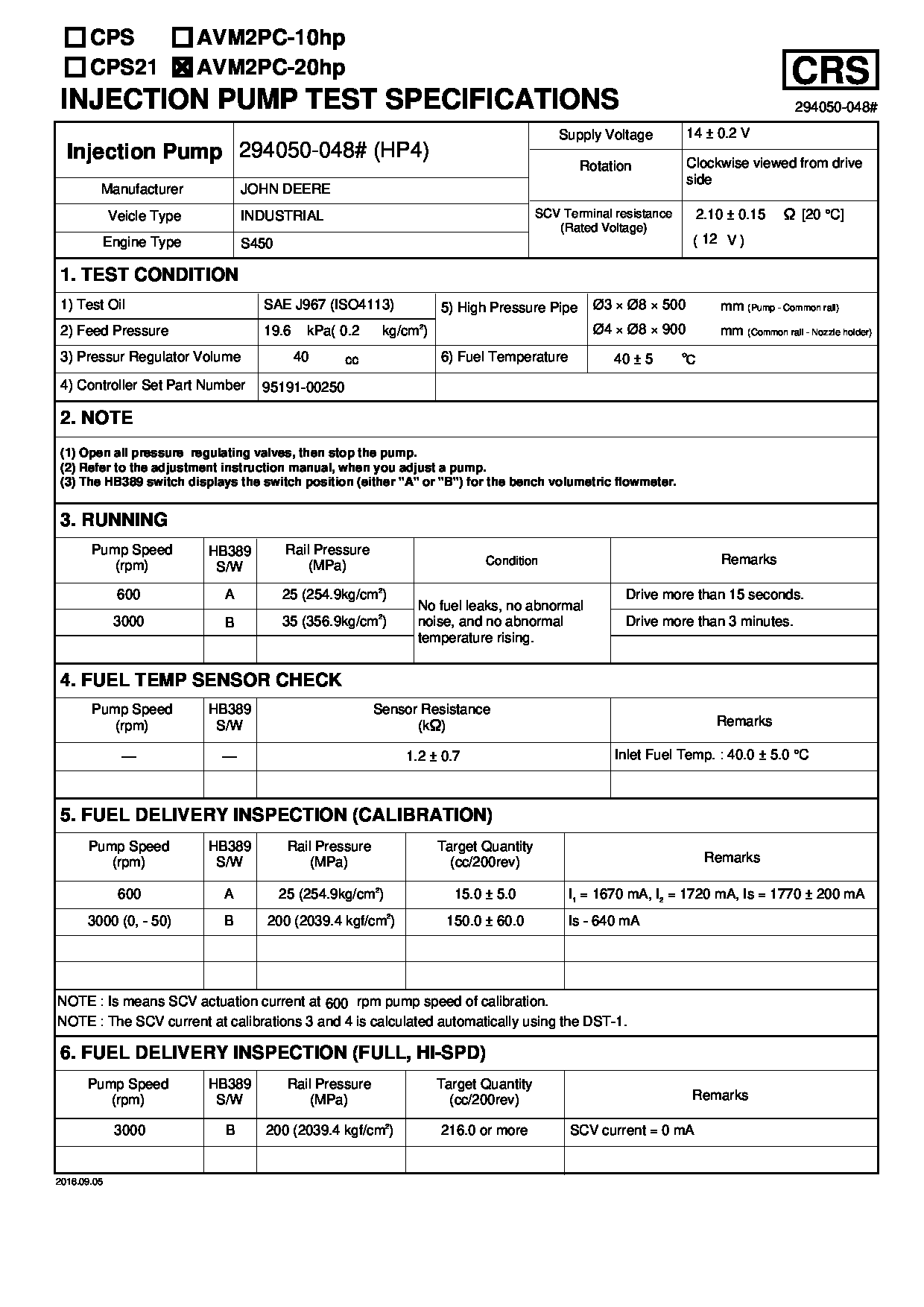
JOHN DEERE
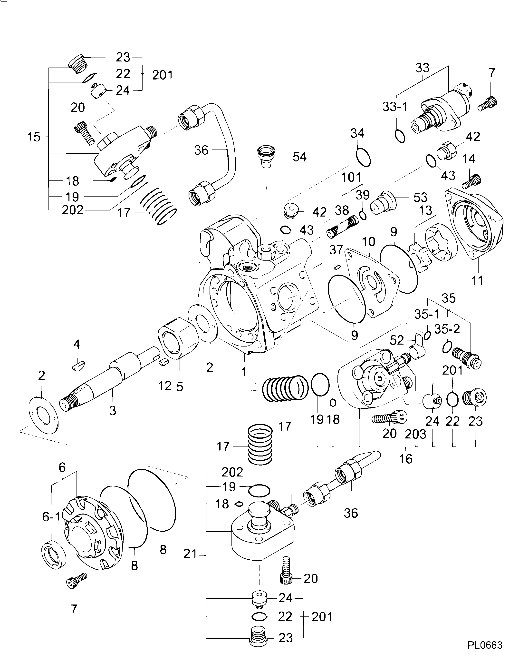
PUMP ASSY, SUPPLY
NB
- * DNJP PRODUCTION 294050-048*
- #..SWITCHED TO DMHU PRODUCTION FROM 1201
Compare Prices: .
As an associate, we earn commssions on qualifying purchases through the links below

$899.30
15 Feb 2025
0.1102[0.05] Pounds
CN: WeiYYii
Diesel Fuel Pump 294050-0480 2940500480 Compatible For S450 Engine
WEIGONG Made of durable plastic and metal, this fuel pump assembly ensures the service life and reliability || The electric fuel pump has excellent design and stable operation, which reduces the risk of mechanical failure and improves the overall reliability || The simple structure of electric fuel pump makes maintenance more convenient and reduces the maintenance cost of long-term operation || Each fuel pump assembly undergoes rigorous testing to guarantee quality before || Diesel Fuel Pump 294050-0480 2940500480 Compatible For S450 Engine
WEIGONG Made of durable plastic and metal, this fuel pump assembly ensures the service life and reliability || The electric fuel pump has excellent design and stable operation, which reduces the risk of mechanical failure and improves the overall reliability || The simple structure of electric fuel pump makes maintenance more convenient and reduces the maintenance cost of long-term operation || Each fuel pump assembly undergoes rigorous testing to guarantee quality before || Diesel Fuel Pump 294050-0480 2940500480 Compatible For S450 Engine

$794.08
15 Feb 2025
0.1102[0.05] Pounds
CN: Minjianziya mall
RE543262 294050-0480 2940500480 SE502553 Fuel Pump Compatible For John Deere Engine 6.8L 6068 Excavator 210G 250GLC 290GLC 8295R 7200R 755K
NYGDRCOT Manufacturing process: Using advanced manufacturing techniques and high-quality materials, it can work stably for a long time and is not prone to malfunctions. || Driving experience: Its noise is very low, providing you with a quiet and comfortable driving environment. Installation is also very convenient, you don't have to worry about any troubles during the installation process. || Functional testing: Its main function is to extract fuel from the fuel tank and deliver it to the engine's fuel injection system at a certain pressure. Its flow rate and pressure have been precisely designed and rigorously tested. || Quality assurance: It can effectively prevent fuel leakage and motor damage. Even in harsh working environments such as high temperature, high pressure, vibration, etc., it can maintain stable performance and extend its service life. || RE543262 294050-0480 2940500480 SE502553 Fuel Pump Compatible For John Deere Engine 6.8L 6068 Excavator 210G 250GLC 290GLC 8295R 7200R 755K
NYGDRCOT Manufacturing process: Using advanced manufacturing techniques and high-quality materials, it can work stably for a long time and is not prone to malfunctions. || Driving experience: Its noise is very low, providing you with a quiet and comfortable driving environment. Installation is also very convenient, you don't have to worry about any troubles during the installation process. || Functional testing: Its main function is to extract fuel from the fuel tank and deliver it to the engine's fuel injection system at a certain pressure. Its flow rate and pressure have been precisely designed and rigorously tested. || Quality assurance: It can effectively prevent fuel leakage and motor damage. Even in harsh working environments such as high temperature, high pressure, vibration, etc., it can maintain stable performance and extend its service life. || RE543262 294050-0480 2940500480 SE502553 Fuel Pump Compatible For John Deere Engine 6.8L 6068 Excavator 210G 250GLC 290GLC 8295R 7200R 755K
$810.76
22 Dec 2024
0.1102[0.05] pounds
CN: xuelianmaoyi
RE543262 294050-0480 2940500480 SE502553 Fuel Pump Compatible For John Deere Engine 6.8L 6068 Excavator 210G 250GLC 290GLC 8295R 7200R 755K
Gvgsgtyu RE543262 294050-0480 2940500480 SE502553 210G 250GLC 290GLC 8295R 7200R 755K || Easy installation: No complex debugging process required, users can use it directly, greatly saving installation time and labor costs. || Easy to maintain: The product design emphasizes practicality, easy disassembly and cleaning, effectively reducing maintenance costs and time. || Reduce vibration: During the operation of the fuel pump, it can effectively reduce vibration transmission, ensure smooth operation of the equipment, and reduce noise and wear. || Long lifespan: Through advanced manufacturing processes and high-quality materials, the service life of fuel pumps has been effectively extended, improving the overall integrity of the equipment.
Gvgsgtyu RE543262 294050-0480 2940500480 SE502553 210G 250GLC 290GLC 8295R 7200R 755K || Easy installation: No complex debugging process required, users can use it directly, greatly saving installation time and labor costs. || Easy to maintain: The product design emphasizes practicality, easy disassembly and cleaning, effectively reducing maintenance costs and time. || Reduce vibration: During the operation of the fuel pump, it can effectively reduce vibration transmission, ensure smooth operation of the equipment, and reduce noise and wear. || Long lifespan: Through advanced manufacturing processes and high-quality materials, the service life of fuel pumps has been effectively extended, improving the overall integrity of the equipment.
Components :
Scheme #.#:
№
Qty
Part num
Name
Remarks
Manufacture num
Cross reference number
Part num
Firm num
Firm
Name
29405-00480
JOHN DEERE
PUMP ASSY, SUPPLY

Information:
Start By:a. remove rocker arm assemblies and push rods1. Disconnect the governor control linkage. See the 3114 & 3116 Engines Governor Service Manual, Form No. SENR6454.
Do not move the fuel control linkage or the injector racks with out the Injector Compressors [Tool (A)] installed. Damage to the fuel injectors can result. After installation of Tool (A), tap on the top of each fuel injector lightly with a rubber mallet to prevent any binding or side loading in the fuel injectors.
2. When removing the fuel control linkage with the fuel injectors in place, install Tool (A) on the fuel injectors, and slightly compress the injector springs.3. Remove four bolts (1) and fuel control linkage (2). The following steps are for the installation of the fuel control linkage.4. Be sure the two screws in each inboard bracket are loose.5. Put fuel control linkage in position on the cylinder head assembly. Be sure all injector racks are engaged and the small dowel in each mounting bracket is in the proper position before tightening bolts (1). Install four bolts (1), and tighten them as follows: a. Tighten the two outer bearing bracket mounting bolts.b. Tighten the inner bearing bracket(s) mounting bolt(s).c. Position the inner bearing(s) to allow free rotation of the rack control rod.d. Tighten the two screws in on each inner bracket(s) to a torque of 3.5 0.2 N m (31 2 lb in).e. The control rod must rotate when a force of 4.4 N (1 lb) or less is applied to control lever (3) in the direction indicated by arrows.6. Connect the governor control linkage. See the 3114 & 3116 Engines Governor Service Manual, Form No. SENR6454.7. After installation of the rocker arm assemblies and push rods, Check and/or adjust the following: Injector Synchronization, Fuel Setting, Fuel Timing, Valve Lash. See the 3114 & 3116 Diesel Truck Engines Systems Operation Testing & Adjusting module, Form No. SENR6437 to check and/or adjust the above items.End By:a. install rocker arm assemblies and push rods