Rating:
Information pump assy, supply Denso
Product
Fuel Injection Pump
Vehicle engine
L200/TRITON 4D56
Engine
4D56
Serial start-end
1412-
Info
Injector Nozzle
MITSUBISHI
PUMP ASSY, SUPPLY
EA
- *1 SIAM DENSO PRODUCTION SM294000-235#
Compare Prices: .
As an associate, we earn commssions on qualifying purchases through the links below

294000-2350 1460A097 Fuel Injection Pump for Mitsubishi Triton 4D56 2.5L Challenger L200 Euro 4 Engine
HIRINTOL 🔸Replace Part Number: 294000-2350, 2940002350, 1460A097 || 🔸Compatible Model: for Mitsubishi Triton 4D56 2.5L Challenger L200 Euro 4 Engine || 🔸Efficient And Stable: Using advanced technology, it can provide efficient and stable fuel supply to ensure the normal operation of the vehicle. || 🔸Durable And Reliable: Tested and proven many times, it has a long life and reliable quality to keep working under extreme conditions. || 🔸Easy Installation: standard interface design, easy installation, plug and play, no professional skills required.
HIRINTOL 🔸Replace Part Number: 294000-2350, 2940002350, 1460A097 || 🔸Compatible Model: for Mitsubishi Triton 4D56 2.5L Challenger L200 Euro 4 Engine || 🔸Efficient And Stable: Using advanced technology, it can provide efficient and stable fuel supply to ensure the normal operation of the vehicle. || 🔸Durable And Reliable: Tested and proven many times, it has a long life and reliable quality to keep working under extreme conditions. || 🔸Easy Installation: standard interface design, easy installation, plug and play, no professional skills required.

ZGZJYBL Common Rail Fuel Injection Pump for Mitsubishi 4D56 Engine 1460A097 294000-2350 2940002350
ZGZJYBL Item Name:Fuel Injection Pump || Item Number:1460A097 294000-2350 2940002350 || Application:for Mitsubishi 4D56 Engine || Attention: If you are unsure if the product is suitable for your machine model. In order not to delay your use of the parts, please provide your engine nameplate or serial number and part number, and we will help you confirm if it is suitable. To avoid unnecessary returns, please carefully check the product image and part number to ensure that it is the product you want. || Tip: If you need any other parts, please contact us - we are a professional sales team and have many products to offer to you. Many buyers are very satisfied with our service. You can get first-class products and high-quality services from us, believe me, you will have a pleasant shopping experience here.
ZGZJYBL Item Name:Fuel Injection Pump || Item Number:1460A097 294000-2350 2940002350 || Application:for Mitsubishi 4D56 Engine || Attention: If you are unsure if the product is suitable for your machine model. In order not to delay your use of the parts, please provide your engine nameplate or serial number and part number, and we will help you confirm if it is suitable. To avoid unnecessary returns, please carefully check the product image and part number to ensure that it is the product you want. || Tip: If you need any other parts, please contact us - we are a professional sales team and have many products to offer to you. Many buyers are very satisfied with our service. You can get first-class products and high-quality services from us, believe me, you will have a pleasant shopping experience here.

1460A097 HP3 Fuel Injection Pump for Mitsubishi Triton Challenger L200 4D56 Euro 4 Engine - 294000-2350
KoovDem Part Number: 294000-2350, 2940002350, 1460A097 || Compatible Model: for Mitsubishi Triton Challenger L200 4D56 Euro 4 Engine || Effective and Reliable: Utilizing cutting-edge technology, this system delivers effective and reliable fuel supply, guaranteeing smooth vehicle performance. || Rugged and Dependable: With a track record of being rigorously tested and proven, this product offers durability and reliability, ensuring it operates consistently even in the harshest of environments. || Straightforward Installation: With a user-friendly interface, installing this product is a breeze. Simply plug it in and you're good to go, no technical expertise needed.
KoovDem Part Number: 294000-2350, 2940002350, 1460A097 || Compatible Model: for Mitsubishi Triton Challenger L200 4D56 Euro 4 Engine || Effective and Reliable: Utilizing cutting-edge technology, this system delivers effective and reliable fuel supply, guaranteeing smooth vehicle performance. || Rugged and Dependable: With a track record of being rigorously tested and proven, this product offers durability and reliability, ensuring it operates consistently even in the harshest of environments. || Straightforward Installation: With a user-friendly interface, installing this product is a breeze. Simply plug it in and you're good to go, no technical expertise needed.
You can buy:

Components :
Scheme #.#:
№
Qty
Part num
Name
Remarks
Manufacture num
000
[01]
29400-02350
PUMP ASSY, SUPPLY
1460A097
MITSUBISHI
Include in ##:
29400-02350
as PUMP ASSY, SUPPLY
Cross reference number
Part num
Firm num
Firm
Name
29400-02350
1460A097
MITSUBISHI
PUMP ASSY, SUPPLY
2940002350
1460A097
MITSUBISHI
PUMP ASSY, SUPPLY
Information:
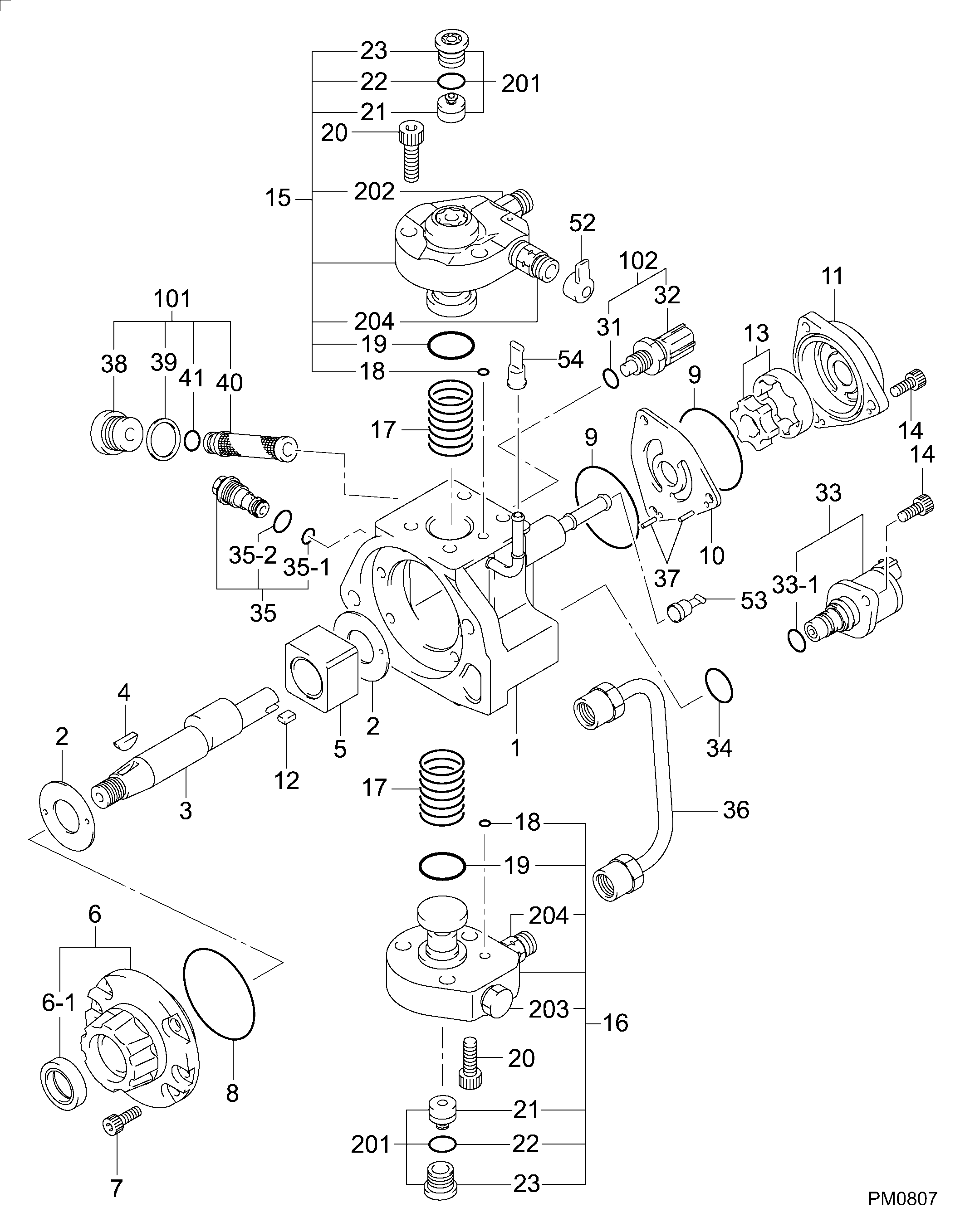
1. Disconnect pressure line (3). Remove two bolts (2).2. Move fuel ratio control (1) up to disengage the fuel ratio control from the lever assembly in the governor. 3. Remove four O-ring seals (4) and screen assembly (5). The following steps are to install the fuel ratio control.4. Inspect, replace and install the four O-ring seals (4) and the screen assembly (5).5. Put the fuel ratio control (1) in position and engage the fuel ratio control with the lever assembly in the governor.6. Install the bolts that hold the fuel ratio control and connect pressure line (3) to the fuel ratio control (1). See Testing And Adjusting for Fuel Ratio Control Adjustment procedure.Disassemble And Assemble Fuel Ratio Control
Start By:a. remove fuel ratio control
Keep all parts clean from contaminants. Contaminants put into the system may cause rapid wear and shortened component life.
1. Remove the two bolts, and the fuel ratio control. Remove O-ring seal (1). 2. Put tooling (A) in a vise as shown so that the station being used is not over the vise jaw. Place the fuel ratio control over the pins in tooling (A). Remove cover (2) and the gasket.
There is spring force behind cover (3). Hold cover (3) in position, and slowly remove the bolts that hold it to release the spring force.
3. Remove cover (3). 4. Remove nut (5) and stop (6). 5. Remove spring (9), washer (7), and diaphragm (10) from retainer (8). Remove retainer (8) from housing (11). 6. Remove nut (16) from extension (15), and remove the extension from retainer (8). Remove valve (12), spring (13) and O-ring seal (14). 7. Remove spring (18), retainer (17) and spring (19). 8. Remove piston assembly (20). 9. Use tooling (B), and remove snap ring (21) and the wave washers from valve assembly (22). Remove piston assembly (23). Remove seal (24). 10. If necessary, remove stem (26) from valve (25).11. Clean and inspect all parts. Make a replacement of all parts that are worn or damaged. The following steps are to assemble the fuel ratio control.12. Assemble stem (26) to valve (25) using 9S3265 Retaining Compound.13. Put seal (24) on piston (23). Install piston (23) on valve assembly (22).14. Put two wave washers in position on valve (22). Use tooling (B) to install the snap ring on the valve assembly.15. Place housing (4) on tooling (A), and put tooling (C) into the bore of the housing. Lubricate tooling (C) with clean engine oil.16. Put a small amount of clean oil on the seal of the piston assembly, and push piston assembly (23) into position with a smooth swift motion.17. Place spring (9), retainer (17) and spring (19) in position in housing (4).18. Put O-ring seal (14) on extension (15). Put spring (13) and valve (12) in position on the extension.19. Lubricate O-ring seal (14) with clean engine oil. Install extension (15) in retainer (8). Install nut (16).20. Put diaphragm (10), washer (7) and spring (9) in position on retainer (8). Install retainer (8).21.