Rating:
Information pump assy, supply Denso
Product
Fuel Injection Pump
Vehicle engine
BUS E494
Engine
E494
Serial start-end
1402-
Info
Injector Nozzle
VECV
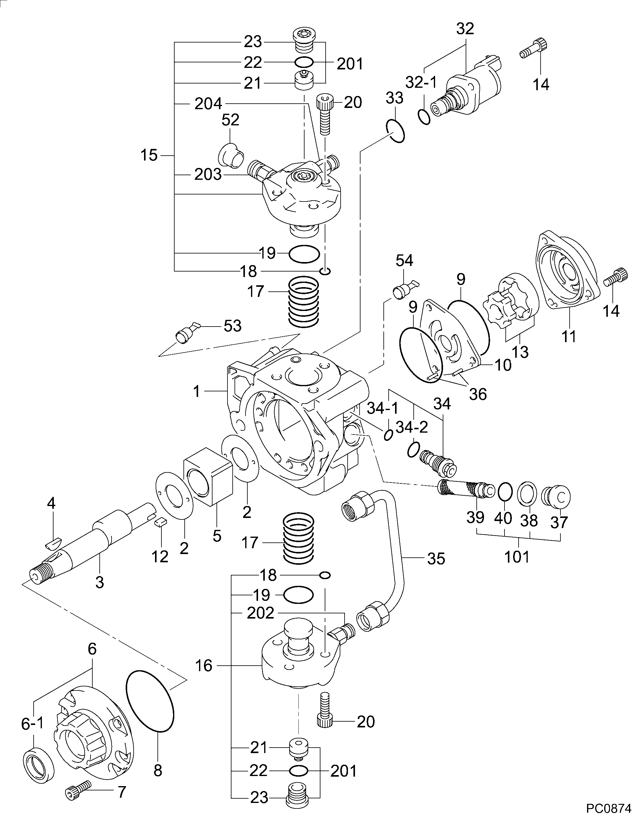
PUMP ASSY, SUPPLY
5M
- * SIAM DENSO PRODUCTION SM294000-202#.
Components :
Scheme #.#:
№
Qty
Part num
Name
Remarks
Manufacture num
000
[01]
29400-02020
PUMP ASSY, SUPPLY
HP3 *
ID319839
VECV
Include in ##:
29400-02020
as PUMP ASSY, SUPPLY
Cross reference number
Part num
Firm num
Firm
Name
29400-02020
ID319839
VECV
PUMP ASSY, SUPPLY
2940002020
ID319839
VECV
PUMP ASSY, SUPPLY


Information:
Take care to avoid mixing metric and inch fasteners. Mismatched or incorrect fasteners can result in mechanical damage or malfunction, or possible personal injury. Original fasteners removed during disassembly should be saved for assembly when possible. If new ones are required, caution must be taken to replace with one that is of same part number and grade.Metric thread fasteners are identified by material strength (grade) numbers on bolt heads and nuts. Numbers on bolts will be 8.8, 10.9, etc. Numbers on nuts will be 8, 10, etc.Engine Design
3116 Cylinder And Valve LocationBore ... 105.025 0.025 mm (4.1348 .0010 in)Stroke ... 127 mm (5.0 in)Displacement ... 6.6 liter (403 cu in)Number Of Cylinders ... 6Cylinder Arrangement ... in-lineValves Per Cylinder ... 2Valve Clearance Setting Intake ... 0.38 mm (.015 in)Exhaust ... 0.64 mm (.025 in)Type of Combustion ... Direct InjectionFiring Order ... 1-5-3-6-2-4Direction of Crankshaft Rotation (when seen from flywheel end) ... counterclockwise Front end of engine is opposite the flywheel end. Left side and right side of engine are as seen from flywheel end. No. 1 cylinder is the front cylinder.Fuel System
Fuel System Schematic
(1) Screen. (2) Inlet check valve. (3) Fuel transfer pump (integral with governor). (4) Outlet check valve. (5) Fuel filter. (6) Cylinder head. (7) Pressure regulating orifice. (8) Check Valve. (9) Primary fuel filter (if equipped). (10) Fuel tank. (A) Fuel priming pump (if equipped).Fuel from the fuel tank is pulled through an in-line screen (1) by fuel transfer pump (3). The fuel transfer pump is integral with the governor. Fuel is sent from the fuel transfer pump through fuel filter (5) and to a drilled passage in cylinder head (6). The drilled passage intersects a gallery around each unit injector to provide a continuous flow of fuel to all injectors. Unused fuel exits the cylinder head and passes through pressure regulating orifice (7) and check valve (8) before returning to fuel tank (10). Orifice (7) is located in the fuel return tube assembly. This pressure regulating orifice ensures adequate fuel gallery pressure for low idle fuel flows. Check valve (8) prevents bleed-off of fuel from the cylinder head during engine shutdown.When there is air on the inlet side of the fuel system, fuel priming pump (A) (if equipped) may be used to fill the fuel filter and fuel gallery (in the cylinder head), from the fuel tank before the engine is started. When the priming pump is used, check valves located in the fuel priming pump control the movement of fuel through the low pressure side of the system which removes air from the fuel lines and components back into the fuel tank.
Fuel Filter Lines Group
(3) Fuel transfer pump (integral with governor). (5) Fuel filter. (6) Cylinder head. (11) Fuel outlet port (to tank). (12) Fuel inlet port (to fuel transfer pump). (13) Fuel filter base. (14) Filtered fuel pressure tap. (15) Tube assembly (from fuel filter base to cylinder head fuel gallery in cylinder head). (16) Tube assembly (from transfer