Rating:
Information pump assy, supply Denso
Product
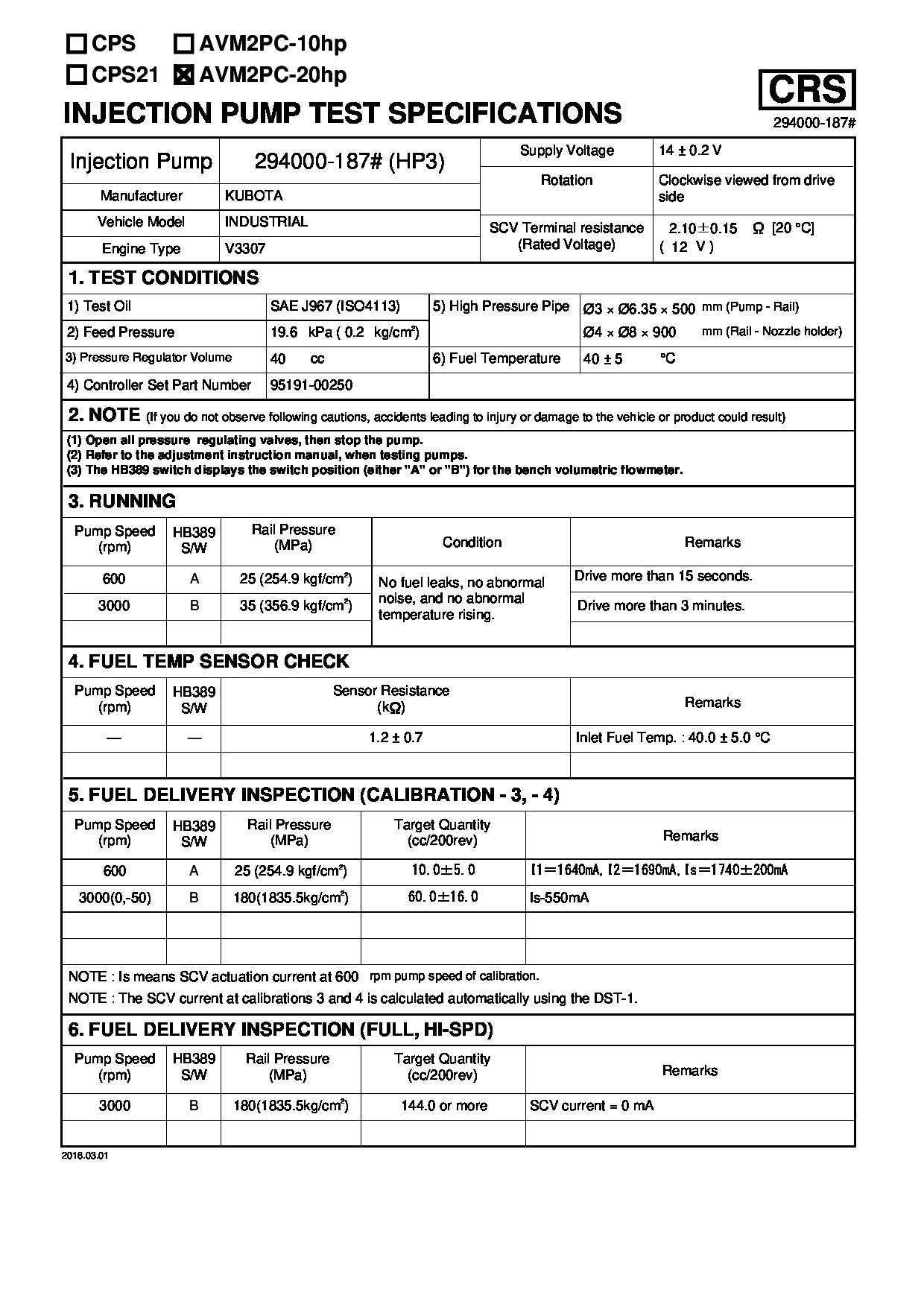
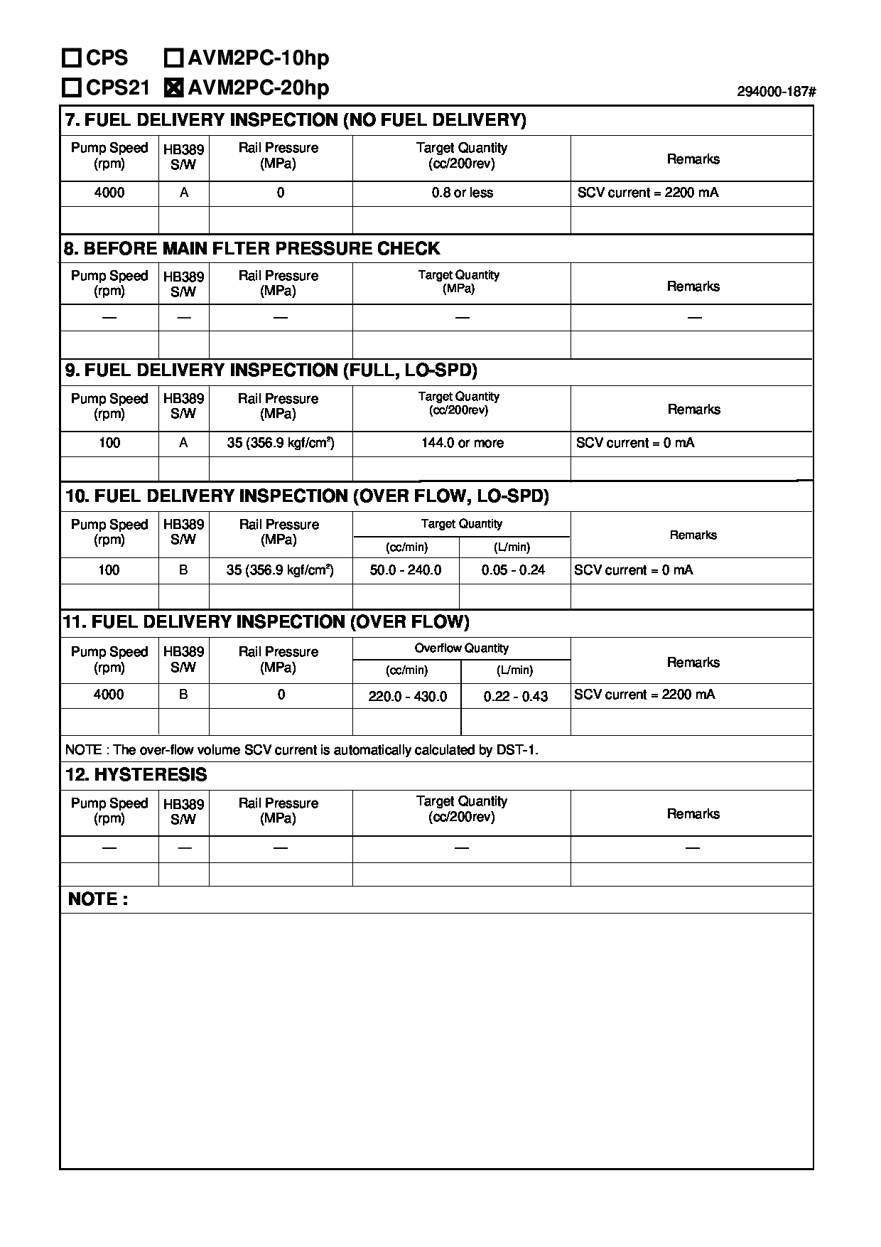
Fuel Injection Pump
Vehicle engine
INDUSTRIAL V3307
Engine
V3307
Serial start-end
1210-
Info
Injector Nozzle
Compare Prices: .
As an associate, we earn commssions on qualifying purchases through the links below

Compatible with Kubota V3307 Engine Fuel Injection Pump 1J77050500 294000-1870 294000-1872 1J770-50500 for 242D 236D 236D3 242D3 246D 246D3 257D 257D3 259D 259D3 262D 262D3 277D 279D Skid Steer
KoovDem Part Number:294000-0422 2940000422 || Part Name: Fuel Injection Pump || Engineered for optimal compatibility with Mazda RF7J diesel engines, this product is the perfect choice for efficient performance. Specifically designed for use with Mazdas diesel engine RF7J, it offers superior functionality and reliability. Tailored to work seamlessly with Mazdas RF7J diesel engine, it is an ideal choice for diesel engine enthusiasts. || Package includes: 1 Fuel Injection Pump with the part number 294000-0422 (2940000422).
KoovDem Part Number:294000-0422 2940000422 || Part Name: Fuel Injection Pump || Engineered for optimal compatibility with Mazda RF7J diesel engines, this product is the perfect choice for efficient performance. Specifically designed for use with Mazdas diesel engine RF7J, it offers superior functionality and reliability. Tailored to work seamlessly with Mazdas RF7J diesel engine, it is an ideal choice for diesel engine enthusiasts. || Package includes: 1 Fuel Injection Pump with the part number 294000-0422 (2940000422).

$1,057.30
20 Feb 2025
0.1102[0.05] pounds
CN: xuelianmaoyi
Diesel High Pressure Fuel Pump 294000-0494 8-97381555-1 294050-0423 294000-0552 294000-0950 294000-1872 294000-1870
Gvgsgtyu High Pressure Fuel Pump || 294000-0494 8-97381555-1 294050-0423 294000-0552 294000-0950 294000-1872 294000-1870 || Easy installation: No complex debugging process required, users can use it directly, greatly saving installation time and labor costs. || Easy to maintain: The product design emphasizes practicality, easy disassembly and cleaning, effectively reducing maintenance costs and time. || Reduce vibration: During the operation of the fuel pump, it can effectively reduce vibration transmission, ensure smooth operation of the equipment, and reduce noise and wear. || Long lifespan: Through advanced manufacturing processes and high-quality materials, the service life of fuel pumps has been effectively extended, improving the overall integrity of the equipment.
Gvgsgtyu High Pressure Fuel Pump || 294000-0494 8-97381555-1 294050-0423 294000-0552 294000-0950 294000-1872 294000-1870 || Easy installation: No complex debugging process required, users can use it directly, greatly saving installation time and labor costs. || Easy to maintain: The product design emphasizes practicality, easy disassembly and cleaning, effectively reducing maintenance costs and time. || Reduce vibration: During the operation of the fuel pump, it can effectively reduce vibration transmission, ensure smooth operation of the equipment, and reduce noise and wear. || Long lifespan: Through advanced manufacturing processes and high-quality materials, the service life of fuel pumps has been effectively extended, improving the overall integrity of the equipment.

$569.90
19 Sep 2024
CN: HIRINTOL-shop
294000-1870 294000-1872 1J770-50500 Fuel Injection Pump for Kubata V3700 V3307-CR-TE4 Engine SVL65-2 SVL75-2 KX057 KX080 U55 M6060 M7060 R530 R540 R630 R640 Tractor
HIRINTOL 🔸Replace Part Number: 294000-1870, 294000-1871, 294000-1872, 294000-1873, 294000-1874, 294000-1875, 294000-1876, 1J770-50500. || 🔸Engine Model: For Kubata Engine V3700 V3307-CR-TE4 4CYL. || 🔸Compatible Model: For Kubota Track Loader: SVL65-2, SVL65-2C, SVL75-2, SVL75-2C; For Kubota Excavator: KX057-4, KX057-5, KX080-4S, KX080-4S2, U55-4, U55-5; For Kubota Wheel Loader: R530, R540, R630, R640. || 🔸Compatible Model: For Kubota Tractor: M4-071HDC12, M4D-061HDC12, M4D-071HDC12, M6060HDC, M6060HFC, M7060HDC, Fit for M7060HDC12, M7060HFC; For Kubota Skid Steer Loader: SSV65, SSV65C, SSV65P, SSV65PC, SSV75, SSV75C, SSV75P, SSV75PC . || 🔸Efficient And Stable: Using advanced technology, it can provide efficient and stable fuel supply to ensure the normal operation of the vehicle.
HIRINTOL 🔸Replace Part Number: 294000-1870, 294000-1871, 294000-1872, 294000-1873, 294000-1874, 294000-1875, 294000-1876, 1J770-50500. || 🔸Engine Model: For Kubata Engine V3700 V3307-CR-TE4 4CYL. || 🔸Compatible Model: For Kubota Track Loader: SVL65-2, SVL65-2C, SVL75-2, SVL75-2C; For Kubota Excavator: KX057-4, KX057-5, KX080-4S, KX080-4S2, U55-4, U55-5; For Kubota Wheel Loader: R530, R540, R630, R640. || 🔸Compatible Model: For Kubota Tractor: M4-071HDC12, M4D-061HDC12, M4D-071HDC12, M6060HDC, M6060HFC, M7060HDC, Fit for M7060HDC12, M7060HFC; For Kubota Skid Steer Loader: SSV65, SSV65C, SSV65P, SSV65PC, SSV75, SSV75C, SSV75P, SSV75PC . || 🔸Efficient And Stable: Using advanced technology, it can provide efficient and stable fuel supply to ensure the normal operation of the vehicle.
Components :
Scheme #.#:
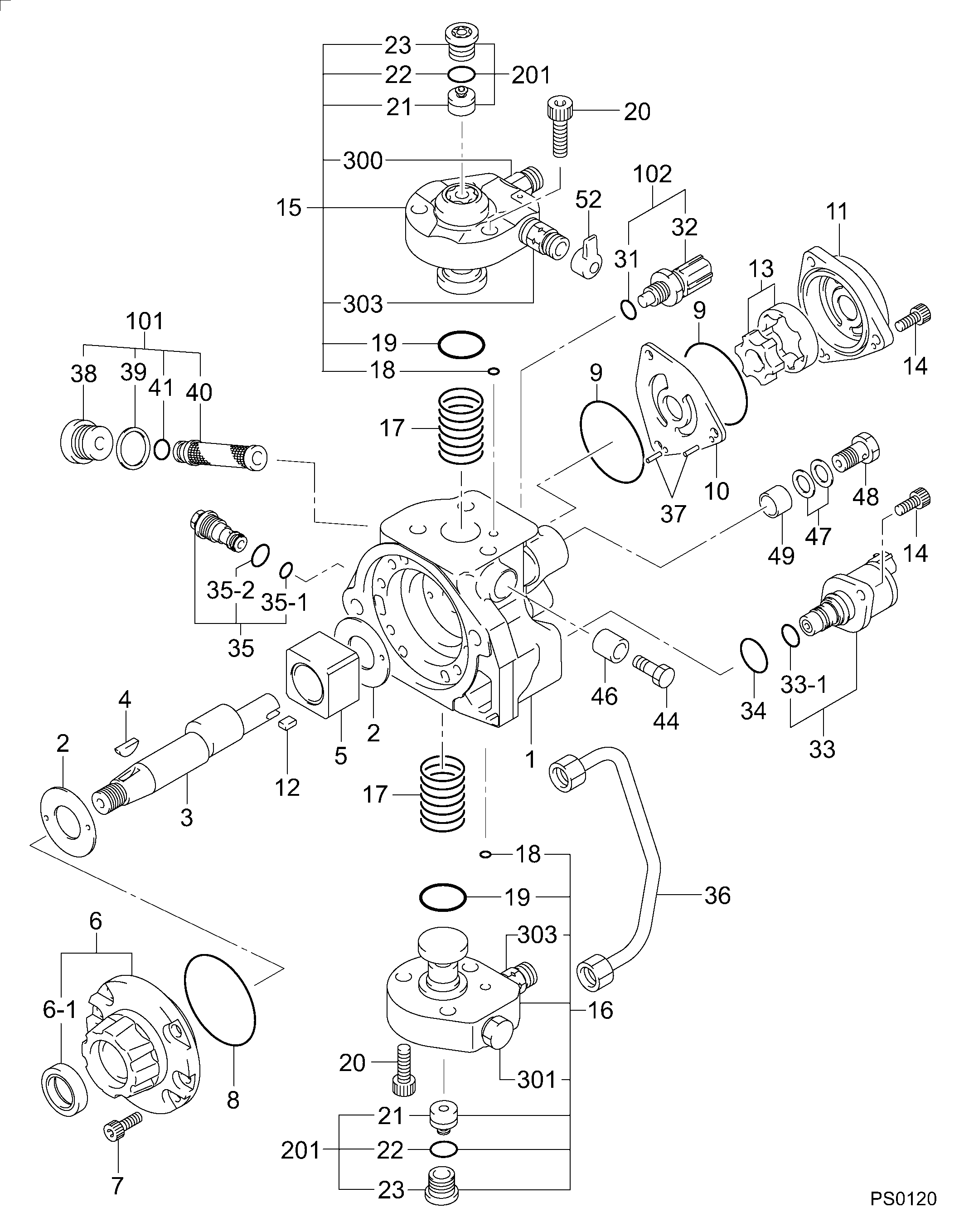
№
Qty
Part num
Name
Remarks
Manufacture num
000
[01]
29400-01870
PUMP ASSY, SUPPLY
HP3
1J770-50501
KUBOTA
Include in ##:
29400-01870
as PUMP ASSY, SUPPLY
Cross reference number
Part num
Firm num
Firm
Name
29400-01870
1J770-5050
PUMP ASSY, SUPPLY
2940001870
1J770-50501
KUBOTA
PUMP ASSY, SUPPLY
2940001870
1J770-50502
KUBOTA
PUMP ASSY, SUPPLY
2940001870
1J770-50503
KUBOTA
PUMP ASSY, SUPPLY
2940001870
1J770-50504
KUBOTA
PUMP ASSY, SUPPLY
2940001870
1J770-50505
KUBOTA
PUMP ASSY, SUPPLY
Information:
1. Disconnect oil supply line (1) and oil drain tube (2). Remove the four mounting nuts and remove the turbocharger. Remove the gasket. The following steps are for the installation of the turbocharger.2. Apply 5P3931 Anti-Seize to turbocharger mounting studs. Position turbocharger gasket and turbocharger, then Install the four mounting nuts. Tighten the four mounting nuts to a torque of 54 5 N m (40 4 lb.ft.).3. Position gaskets and install drain tube (2) and supply line (1).Disassemble And Assemble Turbocharger
Start By:a. remove turbocharger 1. Remove bolts (1) and (2). Remove the compressor and turbine housings.2. Remove nut (3) and compressor wheel (4). Slide out turbine wheel (5) and shaft.3. Remove adapter plate snap ring (6).4. Use two screwdrivers and remove adapter plate (7).5. Remove bushings (8), spacers (9), and seals (10).6. Remove snap ring (11) and bushing (12).7. Remove snap ring (13) and bushing (14). The following steps are for the assembly of the turbocharger.8. Install bushing (12) and snap ring (11). Repeat for bushing (14) and snap ring (13).9. With th seals and shield (15) in place, install shaft and turbine wheel assembly (5).10. Install the spacers, bushings, plate, seals and adapter plate. Install the snap ring (not illustrated).
Do not allow any of the 7M7456 Locktite to get on the shaft. Damage to the turbocharger may occur.
11. Install compressor wheel (4) on the shaft. Put one drop of 7M7456 Locktite on the threads and install nut (3). Tighten nut (3) to a torque of 15.6 .7 N m (138 6 lb.in.).12. Position the turbine and compressor housings. Put 5P3931 Anti-Seize Compound on the bolts and install. Tighten bolts (1) for the compressor cover to a torque of 7.3 .6 N m (65 5 lb.in.). Tighten bolts (2), for the turbine housing to a torque of 15.8 .6 N m (140 5 lb.in.).End by:a. Install turbocharger