Rating:
Information pump assy, supply Denso
Compare Prices: .
As an associate, we earn commssions on qualifying purchases through the links below

SINOCMP 1J502-50501 1J502-50502 1J502-50503 1J502-50504 294000-1730 294000-1731 294000-1732 Fuel Injection Pump for Kubota V3800 V3800DI Diesel Engine & for Bobcat Loader S750 S770 S850 T750 T770 T870
SINOCMP 【Accurate】installation and use our excavator parts. Please find the suitable product based on the old part number and machine model. || 【Scientific】products pass professional testing and inspection. Not sure what the construction machinery product will do? The adaptable products, safe using operation and easy installation. || 【Use】construction machinery product must be in accordance with operating procedures to avoid accidents. We will provide matching product usage guidance and professional product operation suggestions. || 【Key】construction machinery equipment meaning of existence? It is to bring convenience to life. In order to avoid the trouble of frequent replacement, strictly require product quality and improve service life. || 【Part Number】1J502-50501 1J502-50502 1J502-50503 1J502-50504 294000-1730 294000-1731 294000-1732
SINOCMP 【Accurate】installation and use our excavator parts. Please find the suitable product based on the old part number and machine model. || 【Scientific】products pass professional testing and inspection. Not sure what the construction machinery product will do? The adaptable products, safe using operation and easy installation. || 【Use】construction machinery product must be in accordance with operating procedures to avoid accidents. We will provide matching product usage guidance and professional product operation suggestions. || 【Key】construction machinery equipment meaning of existence? It is to bring convenience to life. In order to avoid the trouble of frequent replacement, strictly require product quality and improve service life. || 【Part Number】1J502-50501 1J502-50502 1J502-50503 1J502-50504 294000-1730 294000-1731 294000-1732

Fuel Injection Pump CR HP3 294000-1730 294000-1731 294000-1732 Fits for Kubota V3800 Engine Fits for Bobcat A770 S750 S770 S850 T750 T770 T870 Loader
SXCCGMGQ Part Name:Fuel Injection Pump CR HP3 || Part Number:294000-1730 294000-1731 294000-1732 || Application: Fits for Kubota V3800 Engine Fits for Bobcat A770 S750 S770 S850 T750 T770 T870 Loader || Easy installation: Standardized interface design, easy installation, no additional modification, users can easily complete replacement and maintenance. || Trustworthy: This product through strict quality testing, to provide reliable product quality and after-sales service, so that you use no worries.
SXCCGMGQ Part Name:Fuel Injection Pump CR HP3 || Part Number:294000-1730 294000-1731 294000-1732 || Application: Fits for Kubota V3800 Engine Fits for Bobcat A770 S750 S770 S850 T750 T770 T870 Loader || Easy installation: Standardized interface design, easy installation, no additional modification, users can easily complete replacement and maintenance. || Trustworthy: This product through strict quality testing, to provide reliable product quality and after-sales service, so that you use no worries.

IMIFAFTAbT Fuel Injection Pump 294000-1730 294000-1731 294000-1732 Fits For Kubota V3800 Engine Fits For Bobcat Loader A770 S750 S770 S850 T750 T770 T870
IMIFAFTAbT Part Name:Fuel Injection Pump 294000-1730 294000-1731 294000-1732 || Part Number:294000-1730 294000-1731 294000-1732 1J50250503 1J50250504 || APPlication: Fits For Kubota V3800 Engine for Bobcat Loader A770 S750 S770 S850 T750 T770 T870 || If you are not sure if the product is suitable please leave us a message and send us your original || product picture and part number and we will send the correct part after confirmation
IMIFAFTAbT Part Name:Fuel Injection Pump 294000-1730 294000-1731 294000-1732 || Part Number:294000-1730 294000-1731 294000-1732 1J50250503 1J50250504 || APPlication: Fits For Kubota V3800 Engine for Bobcat Loader A770 S750 S770 S850 T750 T770 T870 || If you are not sure if the product is suitable please leave us a message and send us your original || product picture and part number and we will send the correct part after confirmation
Include in ##:
Cross reference number
Part num
Firm num
Firm
Name
29400-01732
1J502-5050
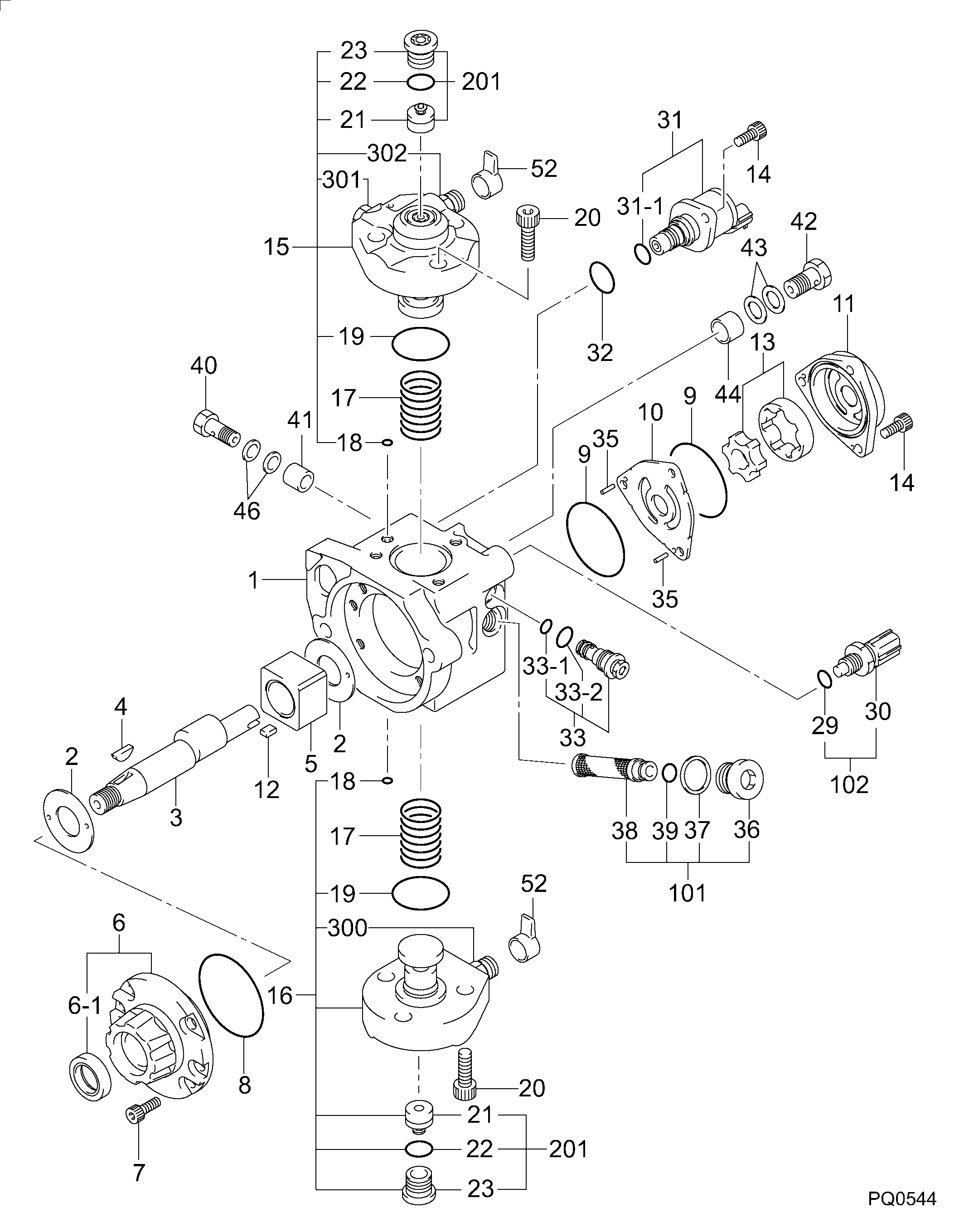
PUMP ASSY, SUPPLY
Information:
1. Drain the cooling system. 2. Loosen hose clamps (1) and (3). Disconnect hoses (2) and (4). 3. Support pump (5) and remove four bolts (6). 4. Remove elbow (7) and the gasket. The following steps are to install the water pump.5. Install a new gasket and elbow (7).6. Put the water pump (5) and elbow (7) in position and install four bolts (6).7. Put hoses (2) and (4) in position on elbow (7) and tighten the clamps (1) and (3).8. Fill the cooling system to the correct level. See the Maintenance Manual.
Perform Scheduled Oil Sampling after performing service work to check for coolant leakage and contaminants left in the system following repair. Contaminants put into the system may cause rapid wear and shortened component life.
Disassemble And Assemble Water Pump
Start By:a. remove water pump
Keep all parts clean from contaminants. Contaminants put into the system may cause rapid wear and shortened component life.
1. Remove bolt (15) and the washer. Remove bearing (12) and gear (10) as a unit.2. Use tooling (A), (C) and a press, and remove bearing (12) from gear (10).3. Remove snap ring (8) with tool (B).4. Remove two bolts (1), the washers, cover (14) and gasket (2) from water pump housing (18).5. Loosen bolt (13) approximately 6.4 mm (.25 in). Hit the bolt with a soft hammer to loosen impeller (16).6. Remove bolt (13), washer (11), impeller (16), spring (3) and seal assembly (4).7. Remove bearing (7) and shaft (9) as a unit.8. Use tooling (A), (C) and a press to remove bearing (7).9. Remove ceramic seal (5) and seal (17).10. Use tool (C) to remove lip-type seal (6). The following steps are for assembly of the water pump.11. Install lip-type seal (6) in water pump housing (18) with tool (C). The lip of the seal must be toward the bearings. Put clean engine oil on the lip of the seal.12. Install shaft (9) in bearing (7) with a press.13. Install shaft (9) and bearing (7) as a unit in water pump housing (18).14. Install snap ring (8) with tool (B).
Clean water only is permitted for use as a lubricant for assembly. Do not damage or put hands on the wear surface of the carbon ring or the ceramic ring. Install the ceramic ring with the smoothest face of the ring toward the carbon seal assembly.
15. Put ceramic ring (5) in position in seal (17). Use hand pressure and tool (D) to install the ceramic ring.16. Remove spring (3) from seal assembly (4). Use hand pressure and tool (D) to install the seal assembly. Push seal assembly (4) on shaft (9) until it makes light contact with ceramic ring (5).17. Install spring (3) on seal assembly (4). Put impeller (16) in position on shaft (9), and install washer (11) and bolt (13). Tighten bolt (13) to a torque of 38.0 1.5 N m (28 1 lb ft).18. Put gasket (2) and cover (14) in position and install the two washers and bolts (1).19. Install