Rating:
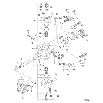
Information pump assy, supply Denso
Product
Fuel Injection Pump
Vehicle engine
INDUSTRIAL V3800
Engine
V3800
Serial start-end
1111-
Info
Injector Nozzle
095000-9690
Injector nozzle:
0950009690
Compare Prices: .
As an associate, we earn commssions on qualifying purchases through the links below
IMIFAFTAbT Fuel Injection Pump 294000-1730 294000-1731 294000-1732 Fits For Kubota V3800 Engine Fits For Bobcat Loader A770 S750 S770 S850 T750 T770 T870
IMIFAFTAbT Part Name:Fuel Injection Pump 294000-1730 294000-1731 294000-1732 || Part Number:294000-1730 294000-1731 294000-1732 1J50250503 1J50250504 || APPlication: Fits For Kubota V3800 Engine for Bobcat Loader A770 S750 S770 S850 T750 T770 T870 || If you are not sure if the product is suitable please leave us a message and send us your original || product picture and part number and we will send the correct part after confirmation
IMIFAFTAbT Part Name:Fuel Injection Pump 294000-1730 294000-1731 294000-1732 || Part Number:294000-1730 294000-1731 294000-1732 1J50250503 1J50250504 || APPlication: Fits For Kubota V3800 Engine for Bobcat Loader A770 S750 S770 S850 T750 T770 T870 || If you are not sure if the product is suitable please leave us a message and send us your original || product picture and part number and we will send the correct part after confirmation
Fuel Injection Pump 294000-1730 1J502-50501 2940001730 1J50250501 Fits for Kubota V3800 V3800T Engine
Goruvhe ☝Part Name☝:Fuel Injection Pump || ☝Part Number☝:294000-1730 1J502-50501 2940001730 1J50250501 || ☝Application☝:Fits for Kubota V3800 V3800T Engine || NOTE: To avoid unavoidable returns! Before purchasing, please compare with the old parts and part numbers to verify their accuracy before making a purchase. || Tips: The product images are for reference only. If you find any discrepancies with your actual product, please contact us promptly and we will respond as soon as possible!
Goruvhe ☝Part Name☝:Fuel Injection Pump || ☝Part Number☝:294000-1730 1J502-50501 2940001730 1J50250501 || ☝Application☝:Fits for Kubota V3800 V3800T Engine || NOTE: To avoid unavoidable returns! Before purchasing, please compare with the old parts and part numbers to verify their accuracy before making a purchase. || Tips: The product images are for reference only. If you find any discrepancies with your actual product, please contact us promptly and we will respond as soon as possible!
1J500-50500 Fuel Injection Pump for Kubota Engine V3800 Tractor M8560 Loader SVL90-2 Fuel Pump Ass'y Replacement Parts 294000-1720 294000-1730
Podafu Part Number: 294000-1720 1J500-50501 294000-1721 294000-172# 294000-1730 294000-173# 1J500-50500 Fuel Injection Pump, Fuel Pump || Application: Fit for Kubota Engine V3800, Tractor M4N-071HD12 M4N-071HDC12 M4N-071HDRC12 M8560, Compact Track Loader SVL90-2. || Perfect Replacement: Crafted from premium materials and meticulously engineered, tailored for specific vehicles. Rigorously tested for leaks and longevity. Easy and quick to install as a seamless replacement. || Make sure to confirm the part number and vehicle model to ensure that the product is compatible with your specific requirements. || By reducing fuel consumption, improving jitter, and enhancing speed smoothness, driving becomes more comfortable while also decreasing monthly fuel expenses.
Podafu Part Number: 294000-1720 1J500-50501 294000-1721 294000-172# 294000-1730 294000-173# 1J500-50500 Fuel Injection Pump, Fuel Pump || Application: Fit for Kubota Engine V3800, Tractor M4N-071HD12 M4N-071HDC12 M4N-071HDRC12 M8560, Compact Track Loader SVL90-2. || Perfect Replacement: Crafted from premium materials and meticulously engineered, tailored for specific vehicles. Rigorously tested for leaks and longevity. Easy and quick to install as a seamless replacement. || Make sure to confirm the part number and vehicle model to ensure that the product is compatible with your specific requirements. || By reducing fuel consumption, improving jitter, and enhancing speed smoothness, driving becomes more comfortable while also decreasing monthly fuel expenses.
Components :
Scheme #.#:
№
Qty
Part num
Name
Remarks
Manufacture num
000
[01]
29400-01730
PUMP ASSY, SUPPLY
HP3
1J502-50501
KUBOTA
Include in ##:
29400-01730
as PUMP ASSY, SUPPLY
Cross reference number
Part num
Firm num
Firm
Name
29400-01730
1J502-5050
PUMP ASSY, SUPPLY
2940001730
1J502-50501
KUBOTA
PUMP ASSY, SUPPLY
2940001730
1J502-50502
KUBOTA
PUMP ASSY, SUPPLY
2940001730
1J502-50503
KUBOTA
PUMP ASSY, SUPPLY
2940001730
1J502-50504
KUBOTA
PUMP ASSY, SUPPLY
2940001730
1J502-50505
KUBOTA
PUMP ASSY, SUPPLY
Information:
Keep all parts clean from contaminants. Contaminants put into the system may cause rapid wear and shortened component life.
1. Remove four bolts (1). Disconnect wires (2) and (3). 2. Remove jake brake (A) by lifting with one hand while holding oil tube (4) to insure it does not come out of jake brake (B).3. Remove jake brake (B). 4. Remove four spacers (5). Install in reverse order.End By:a. install valve cover
Perform Scheduled Oil Sampling on oil wetted compartments after performing service work to check for contaminants left in the system following repair. Contaminants put into the system may cause rapid wear and shortened component life.
Disassemble And Assemble Jake Brake
Start By:a. Remove jake brake
Keep all parts clean from contaminants. Contaminants put into the system may cause rapid wear and shortened component life.
1. Remove oil tubes (1) and (2). Remove the o-ring seals and check for wear or damage. Replace the o-ring seals during assembly if required. 2. Remove snap ring (3), cup (4), spacer (5), springs (6) and (7) and piston (8). 3. Remove three retaining rings (9). Remove clip (10), Springs (11) and (12) and piston (13) from three locations on the jake brake. 4. Remove three bolts (16), washers (15), clips (14) and piston (17). Assemble in reverse order.End By:a. install jake brake
Perform Scheduled Oil Sampling on oil wetted compartments after performing service work to check for contaminants left in the system following repair. Contaminants put into the system may cause rapid wear and shortened component life.


