Rating:
Information pump assy, supply Denso
Product
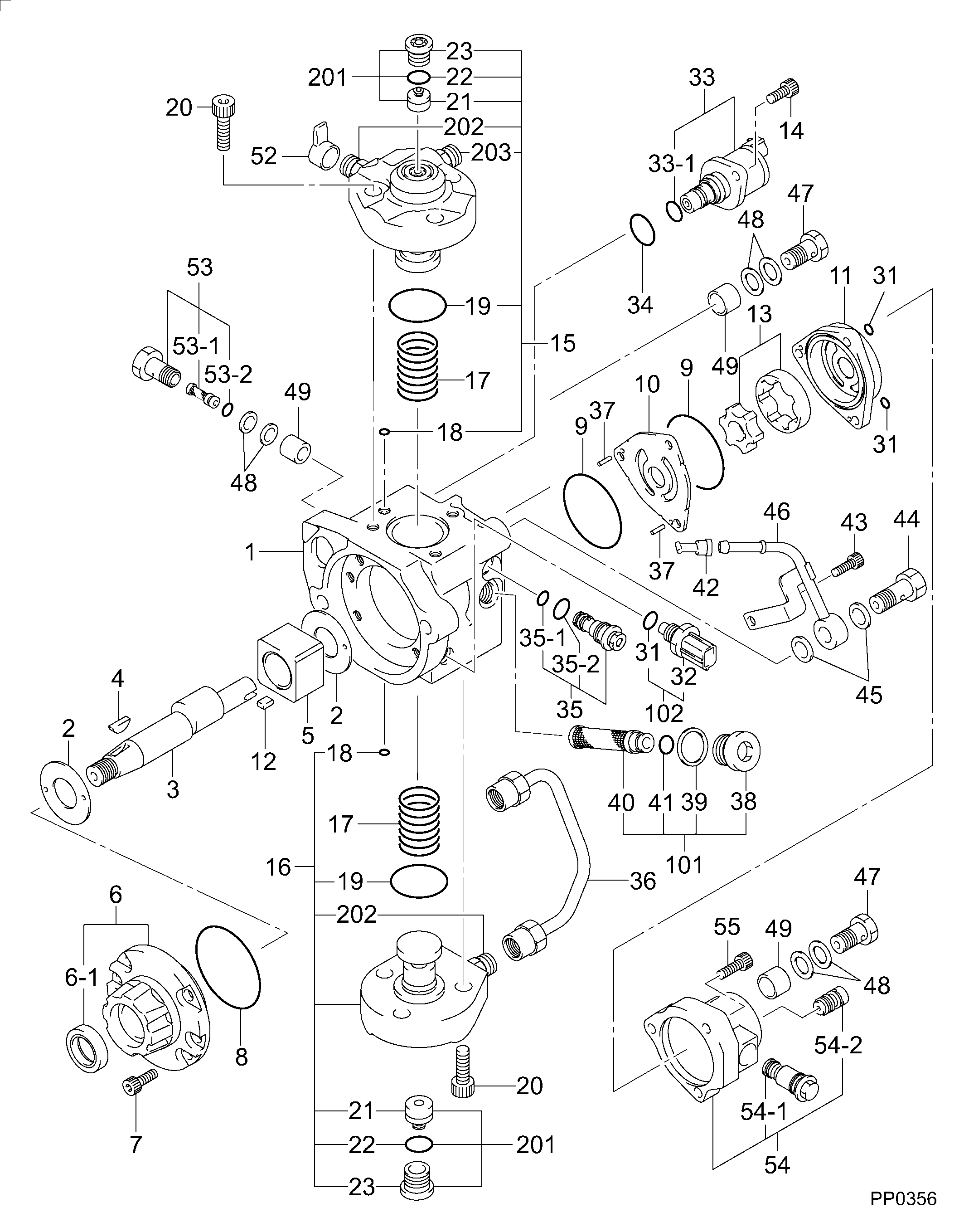
Fuel Injection Pump
Vehicle engine
TRUCK J05E
Engine
J05E
Serial start-end
1106-
Info
Injector Nozzle
Compare Prices: .
As an associate, we earn commssions on qualifying purchases through the links below

YRGGHUI Diesel Injector Pump Fuel Injection Pump 294000-1550 294000-1560 294000-2110,Compatible for Hino J05E
YRGGHUI OEM NO:294000-1550 294000-1560 294000-2110 || Types of automotive components: fuel pump, diesel pump, high-pressure fuel pump components, fuel pump components || Fuel pump: can enhance power, reduce fuel consumption, provide strong power, accelerate smoothly, and ensure the stability of the fuel pump at high temperatures. Make your car full of power || Before purchasing a fuel pump, please confirm if the picture and OEM number match your part! This is really important! If they are not the same component, they cannot be used! All products undergo testing before shipment!! || If you have any questions, please feel free to contact us and we will reply within 24 hours. Please confirm the product based on your vehicle model, year, code, and tag number. thank you. Automotive parts have accurate OEM numbers. Please ensure that the OEM number is suitable for your car
YRGGHUI OEM NO:294000-1550 294000-1560 294000-2110 || Types of automotive components: fuel pump, diesel pump, high-pressure fuel pump components, fuel pump components || Fuel pump: can enhance power, reduce fuel consumption, provide strong power, accelerate smoothly, and ensure the stability of the fuel pump at high temperatures. Make your car full of power || Before purchasing a fuel pump, please confirm if the picture and OEM number match your part! This is really important! If they are not the same component, they cannot be used! All products undergo testing before shipment!! || If you have any questions, please feel free to contact us and we will reply within 24 hours. Please confirm the product based on your vehicle model, year, code, and tag number. thank you. Automotive parts have accurate OEM numbers. Please ensure that the OEM number is suitable for your car
You can buy:

Components :
Scheme #.#:
№
Qty
Part num
Name
Remarks
Manufacture num
Cross reference number
Part num
Firm num
Firm
Name
29400-01560
PUMP ASSY, SUPPLY
2940001560
22100-E0570
HINO
PUMP ASSY, SUPPLY
Information:
It is not necessary to remove the cylinder head assembly for removal of the camshaft.3. Wire the cam roller followers up off of the camshaft as shown. Do this at each cylinder.
Typical Example3. Remove thrust pin (1), and remove camshaft assembly (2) from the engine. The following steps are for the installation of the camshaft assembly.4. Be sure the camshaft assembly is thoroughly clean. Put clean engine oil on the lobes and journals of the camshaft assembly. When installing the camshaft, rotating it in both clockwise and counterclockwise directions will help prevent it from binding in the bearing bores.5. Carefully install camshaft assembly (2) in the engine.
Camshaft Timing
When installing the camshaft assembly, be sure the number one cylinder is at (TDC) top dead center of the compression stroke with the timing pin installed in the flywheel. Camshaft timing is very important. The timing mark on the camshaft drive gear must line up with the idler gear timing mark as shown in the illustration. For more information about timing of engine, refer to the "Specifications" module, Form No. SENR5560.
6. With the camshaft properly timed and positioned, install thrust pin (1). Tighten thrust pin (1) to a torque of 48 7 N m (35 5 lb ft). Remove the wires that were used to hold the cam roller followers up off of the camshaft.End By:a. install front housing groupb. install speed/timing sensorc. install vibration damper and pulleyd. install alternatore. install drive belt and belt tightener groupf. install fuel transfer pumpg. install electronic unit injectorsh. install rocker arm assemblies and push rodsDisassemble & Assemble Camshaft Assembly
Start By:a. remove camshaft assembly1. Wrap camshaft portion of camshaft assembly with paper towels to protect the camshaft from being damaged.
Care must be taken not to allow the camshaft to fall to the floor when pressing it from the drive gear. Also, be sure that a camshaft lobe does not catch on the press plates.
2. Place the camshaft assembly in a press. Press camshaft (3) from drive gear (1).3. Remove woodruff key (2) from the camshaft. The following steps are for the assembly of the camshaft and the gear assembly.4. Install woodruff key (2) in the camshaft.5. Heat drive gear (1) to a maximum temperature of 300 C (572 F) for 30 minutes. Install the drive gear on the end of camshaft (3). Be sure woodruff key (2) is properly aligned and the drive gear makes contact with the shoulder on the end of the camshaft.End By:a. install camshaft assembly