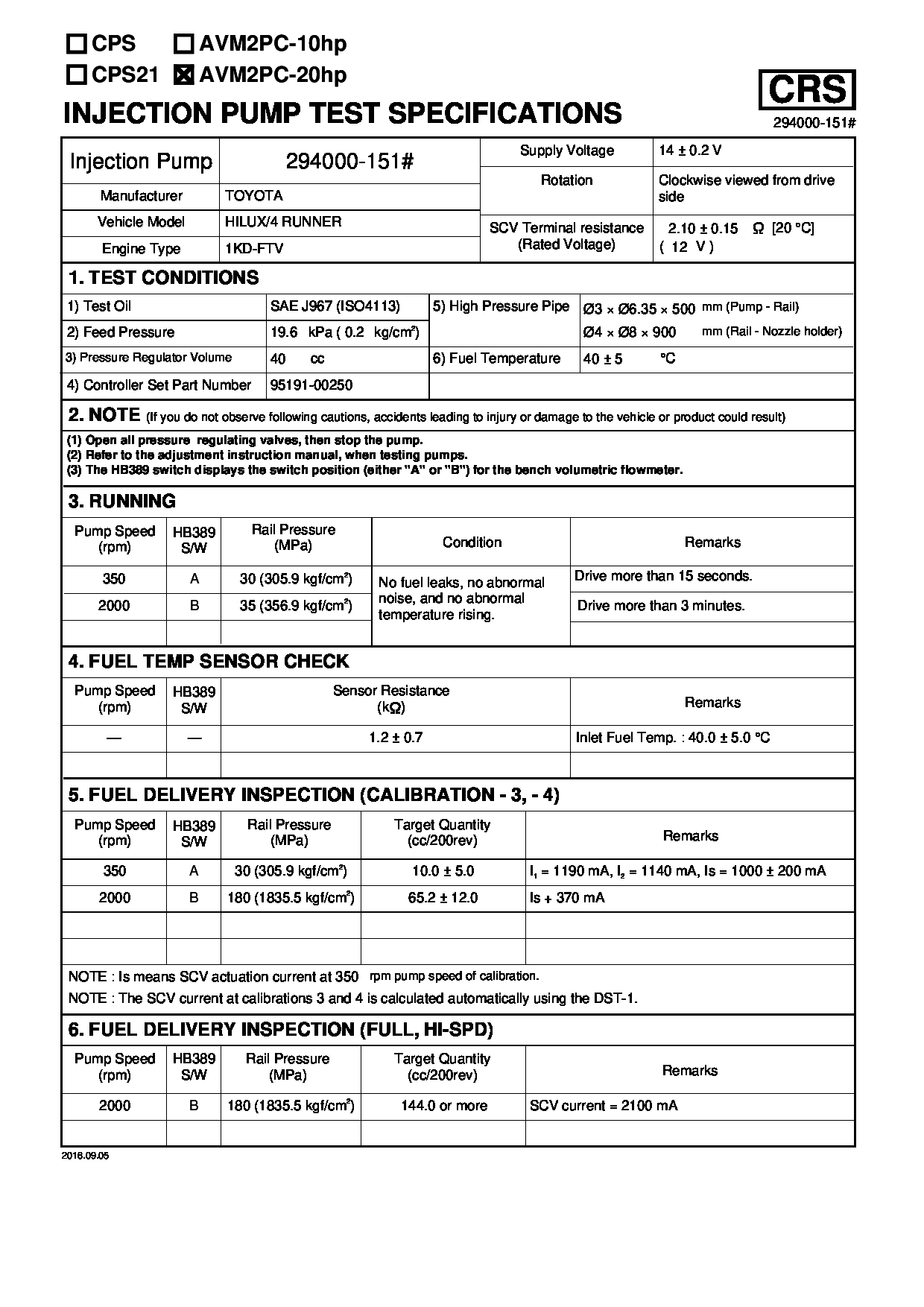
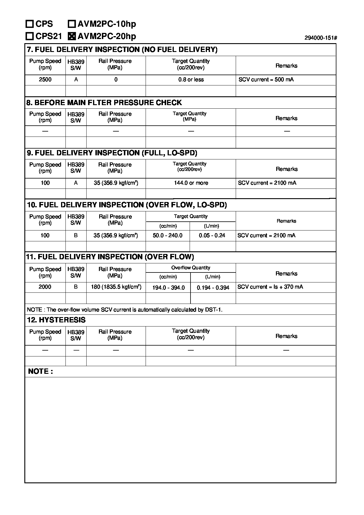
Rating:
Information pump assy, supply Denso
Product
Fuel Injection Pump
Vehicle engine
HILUX 1KD-FTV
Engine
1KD-FTV
Serial start-end
0202-
Info
Injector Nozzle
095000-1050
TOYOTA
PUMP ASSY, SUPPLY
AA
- *1 SIAM DENSO PRODUCTION SM294000-151#
- THIS CAN BE USED IN PLACE OF SM294000-011# AS A SUPPLY.
- #..NEW PARTS ARE INTERCHANGEABLE WITH OLD ONE,
- IF NO.3,4 ARE CHANGED AT THE SAME TIME.
Injector nozzle:
0950001050
Components :
Scheme #.#:
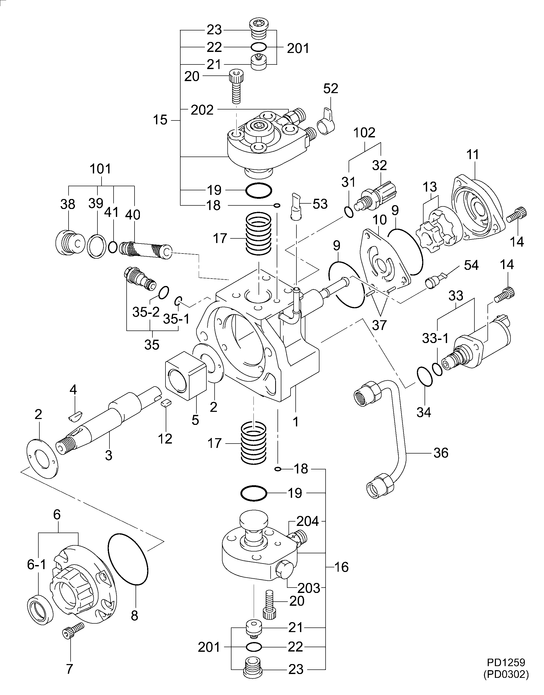
№
Qty
Part num
Name
Remarks
Manufacture num
000
[01]
29400-01510
PUMP ASSY, SUPPLY
22100-0L010
TOYOTA
Include in ##:
29400-01510
as PUMP ASSY, SUPPLY
Cross reference number
Part num
Firm num
Firm
Name
29400-01510
22100-0L01
TOYOTA
PUMP ASSY, SUPPLY
2940001510
22100-0L010
TOYOTA
PUMP ASSY, SUPPLY
Information:
Remove Jacobs Engine Brake
1. Loosen clamp (1), and disconnect breather tube (2) from the hose.2. Remove four bolts (5) that hold the elbow to the inlet manifold. Remove elbow (3) and air pipe (4) as a unit. 3. Remove bolts (7) that hold the valve covers in place. Remove valve covers (6). 4. Disconnect solenoid lead wires (8) and (10) from the terminal in the Jacobs spacer.5. Remove eight Jacobs nuts (9) and four Jacobs bolts that hold the Jacobs spacers to the valve cover bases. Remove Jacobs spacers (11). Do Steps 6 through 13 for each end of the engine. The front half of the engine is shown.6. Remove four Jacobs studs (12) and Jacobs washers. Remove three bolts (13), and remove valve cover base (14). 7. Remove Jacobs nuts (15), Jacobs washers, Jacobs bolts (16) and the Jacobs washers that hold the Jacobs brake housing assembly in place.8. Remove Jacobs brake housing assembly (17). The Jacobs brake for the 3406B Truck Engine has only one support bracket (18).9. Remove Jacobs head bolts (19), and remove Jacobs support brackets (18) from the cylinder head. 10. Remove inner fuel lines (20). 11. Remove Jacobs washers (21) and Jacobs shims (22) from the Jacobs stud assemblies. 12. Remove bolt (24) and two Jacobs stud assemblies (23) that hold the rocker shaft assembly to the head. Remove rocker shaft assembly (25). 13. Remove Jacobs exhaust valve bridges (27) from the exhaust valves only. The intake valves have the Caterpillar intake valve bridges. Remove the Caterpillar intake valve bridges (26). 14. Remove Jacobs engine control switch (29) from the governor housing. Remove Jacobs actuator arm (28).Install Jacobs Engine Brake
Do each step for each end of the engine. The front half is shown.1. Put clean engine oil on the bridges and dowels.2. Install Jacobs exhaust valve bridges (1) and the Caterpillar intake valve bridges (2) on the dowels.3. Keep hand pressure on the bridges, and turn the adjustment screw clockwise until contact is made with the valve stem. Turn the screw an extra 20° to 30°. This will make the dowel straight in the guide and compensate for gap (slack) in the threads. Hold the adjustment screw in this position, and tighten the locknut to a torque of 28 4 N m (21 3 lb.ft.). 4. Put rocker shaft assembly (3) in position on the cylinder head. 5. Install Jacobs washers (4) on the Jacobs stud assemblies (6). Put clean oil on the threads, and install washer and bolt (5) and Jacobs stud assemblies (6). Tighten the center bolt and Jacobs stud assemblies in increments of 70 N m (50 lb.ft.) each until a final torque of 450 N m (330 lb.ft.) is obtained.6. Make an adjustment to the valves to have a clearance of .015 (0.38 mm) for the intake valves and .030 (0.76 mm) for the exhaust valves. Tighten the locknuts to a torque of 28 4 N m (21 3 lb.ft.), and check the