Rating:
Information pump assy, supply Denso
Product
Fuel Injection Pump
Vehicle engine
DUTRO N04C
Engine
N04C
Serial start-end
1208-
Info
24V
Injector Nozzle
Compare Prices: .
As an associate, we earn commssions on qualifying purchases through the links below

Compatible with Hino Diesel Engine N04C Fuel Injection Pump 294000-1460 2940001460
KoovDem Part Number: 294000-1460 2940001460 Note: Please check the fitment carefully before purchase. Or just tell us the part number you need. || Part Name: Fuel Injection Pump || The compact and efficient N04C engine is popular in trucks, buses, and vans due to its reliability and power. Designed for high performance and fuel efficiency, it reduces operating costs. Built with advanced technology and quality construction, it is durable and can handle heavy-duty use. Overall, the N04C engine offers a dependable and smooth driving experience in various applications. || Suitable for use with Hino Diesel Engine N04C || Included in the package: 1 piece of Fuel Injection Pump 294000-1460 (2940001460).
KoovDem Part Number: 294000-1460 2940001460 Note: Please check the fitment carefully before purchase. Or just tell us the part number you need. || Part Name: Fuel Injection Pump || The compact and efficient N04C engine is popular in trucks, buses, and vans due to its reliability and power. Designed for high performance and fuel efficiency, it reduces operating costs. Built with advanced technology and quality construction, it is durable and can handle heavy-duty use. Overall, the N04C engine offers a dependable and smooth driving experience in various applications. || Suitable for use with Hino Diesel Engine N04C || Included in the package: 1 piece of Fuel Injection Pump 294000-1460 (2940001460).
104135-4100 Fuel Injection Pump Compatible with Perkins Engine 404D-22T 404D-22TA
KoovDem Part Number:294000-1460 2940001460 || Part Name: Fuel Injection Pump || Designed for maximum performance and efficiency, this product is tailored for use with the Hino Diesel Engine N04C. Whether you want to boost power or save on fuel, this versatile component is the perfect choice. Its durability and reliability ensure smooth operation with minimal maintenance required. A cost-effective essential for anyone using the Hino Diesel Engine N04C. || Package includes one unit of Fuel Injection Pump 294000-1460 (2940001460).
KoovDem Part Number:294000-1460 2940001460 || Part Name: Fuel Injection Pump || Designed for maximum performance and efficiency, this product is tailored for use with the Hino Diesel Engine N04C. Whether you want to boost power or save on fuel, this versatile component is the perfect choice. Its durability and reliability ensure smooth operation with minimal maintenance required. A cost-effective essential for anyone using the Hino Diesel Engine N04C. || Package includes one unit of Fuel Injection Pump 294000-1460 (2940001460).

$720.00
27 Feb 2025
CN: JP - Construction Ma
294050-0155 22100-E0104 Fuel Injection Pump Compatible for Hino J08E Diesel Engine
JPSMZSC Note: Please confirm that the product shown in the part number is what you need. If you cannot confirm, you can leave us a message and provide your engine serial number and nameplate. || Product Name:Fuel Injection Pump || Part number:294050-0155 22100-E0104 || Application:Compatible for Hino J08E Diesel Engine || Tip: We mainly deal in all parts of the construction machinery series. Our product has stable performance, fast response, high reliability, and easy installation. High quality, most guaranteed. If you have any other requirements, please contact us.
JPSMZSC Note: Please confirm that the product shown in the part number is what you need. If you cannot confirm, you can leave us a message and provide your engine serial number and nameplate. || Product Name:Fuel Injection Pump || Part number:294050-0155 22100-E0104 || Application:Compatible for Hino J08E Diesel Engine || Tip: We mainly deal in all parts of the construction machinery series. Our product has stable performance, fast response, high reliability, and easy installation. High quality, most guaranteed. If you have any other requirements, please contact us.
You can buy:

Components :
Scheme #.#:
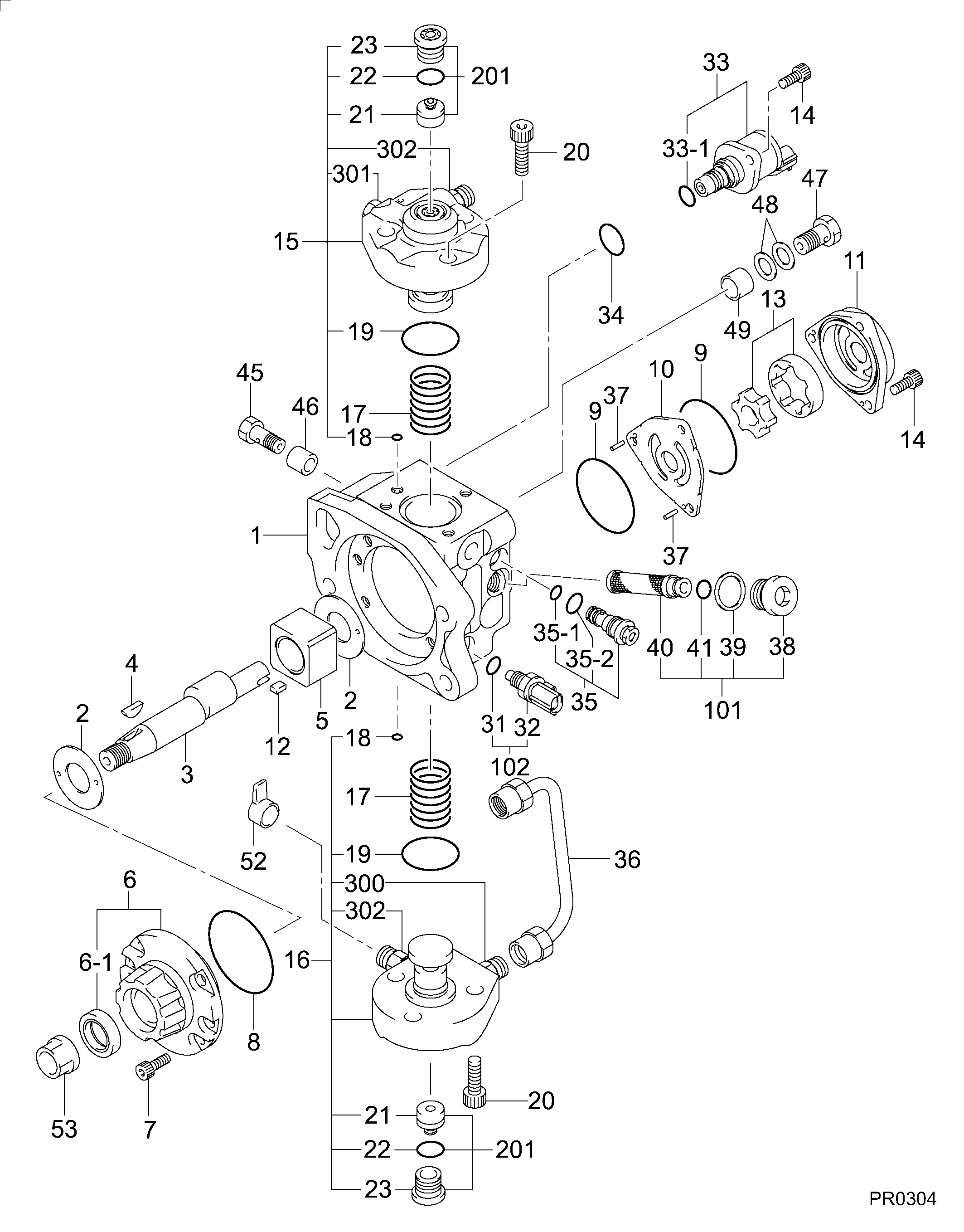
№
Qty
Part num
Name
Remarks
Manufacture num
000
[01]
29400-01460
PUMP ASSY, SUPPLY
HP3
22100-E0560-C
HINO
Include in ##:
29400-01460
as PUMP ASSY, SUPPLY
Cross reference number
Part num
Firm num
Firm
Name
29400-01460
22100-E056
PUMP ASSY, SUPPLY
2940001460
22100-E0560-C
HINO
PUMP ASSY, SUPPLY
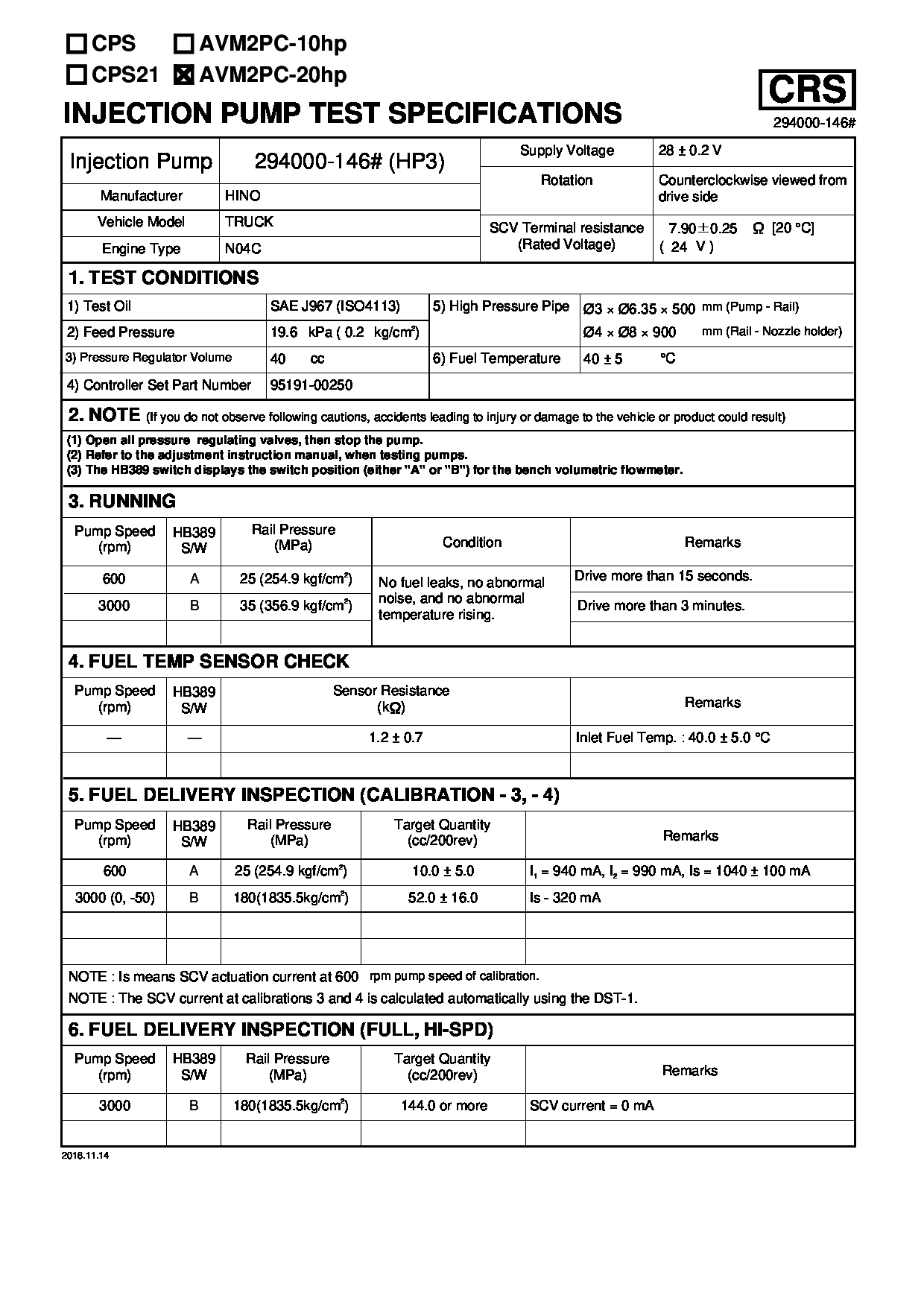
Test Calibration Data:
02EN146000
22100-E0560
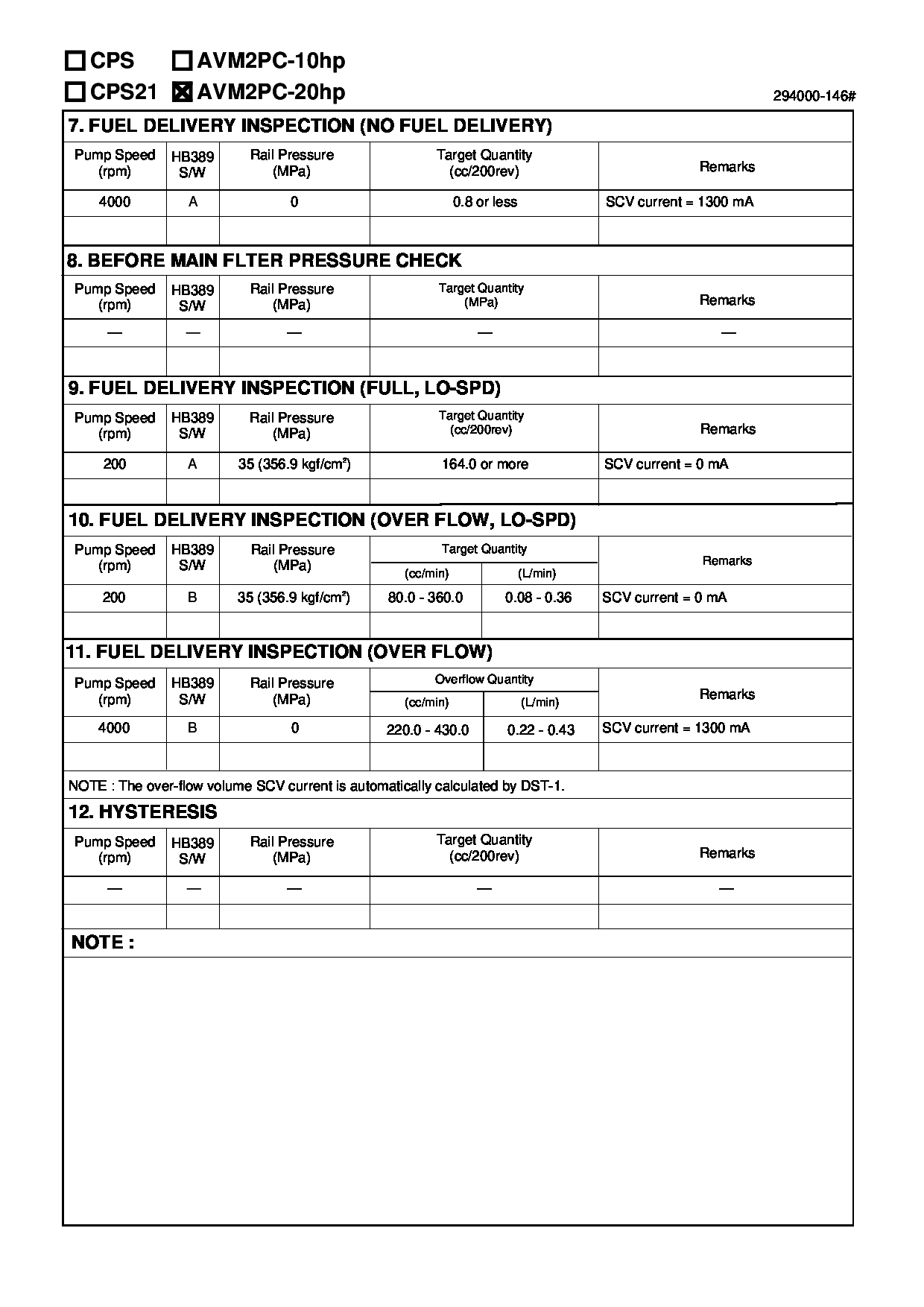
02EN146000
22100-E0560
02EN146000
22100-E0560
02EN146000
22100-E0560
Information:
2. Remove the cylinder liners with tool (A) as shown. The Caterpillar pack pulling tools can be used to remove the cylinder liner, piston and connecting rod as a unit. For more detail, see Special Instruction, Form No. SEHS8554.Install Cylinder Liners
1. Clean the cylinder liners and the liner bores in the cylinder block. 2. Install cylinder liners (1) in the block without the O-ring seals or filler band. 3. Check the cylinder liner projection as follows:a. Install the 3/4"-16 NF bolts, 3 in. (76 mm) long and the 2F126 Washers of tooling (A) on the cylinder block next to each liner. Tighten the bolts evenly, in four steps: 14 N m (10 lb.ft.), 35 N m (26 lb.ft.), 70 N m (50 lb.ft.) and then turn to 95 N m (70 lb.ft.).b. Put the adapter plate and one plate of tooling (A) on top of the liner, and install the remainder of tooling (A). Be sure the bar is in position at the center of the liner. Tighten the bolts evenly, in four steps to a torque of 7 N m (5 lb.ft.), 20 N m (15 lb.ft.), 35 N m (25 lb.ft.) then to 70 N m (50 lb.ft.).c. Check to be sure the distance from the bottom edge of the bar to the top of the cylinder block is the same on both sides of the liner.d. Check the cylinder liner projection with tooling (B) at four locations around the liner. Special Instruction, Form No. SMHS7727, is included with the tool.e. Liner projection must be 0.03 to 0.15 mm (.001 to .006 in.). Measurements on the same liner must not be different by more than 0.05 mm (.002 in.). Average measurements between liners next to each other must not be different by more than 0.05 mm (.002 in.).The maximum difference in the average projection for all cylinder liners under one cylinder head must not be more than 0.10 mm (.004 in.). If the liner is turned in the bore it can make a difference in the liner projection. f. If the liner projection is not 0.03 to 0.15 mm (.001 to .006 in.), check the thickness of the following parts: spacer plate, spacer plate gasket and cylinder liner flange (3). The thickness of the spacer plate must be 8.59 0.03 mm (.338 .001 in.). The thickness of the spacer plate gasket must be 0.20 0.03 mm (.008 .001 in.). The thickness of the cylinder liner flange must be 8.890 0.020 mm (.3500 .0008). The cylinder liner projection can be changed by the correction of the counterbore in the block to a minimum depth of 0.76 mm (.030 in.) with an 8S3140 Cylinder Block Counterboring Tool. See Special Instruction, Form FM055228. A 5N93 Stainless Steel Insert is also available for use after the cylinder block has been counterbored. Special Instruction Form No. SMHS8222 has the correct installation procedure for the insert.4. Put a mark on the liner and block so the
1. Clean the cylinder liners and the liner bores in the cylinder block. 2. Install cylinder liners (1) in the block without the O-ring seals or filler band. 3. Check the cylinder liner projection as follows:a. Install the 3/4"-16 NF bolts, 3 in. (76 mm) long and the 2F126 Washers of tooling (A) on the cylinder block next to each liner. Tighten the bolts evenly, in four steps: 14 N m (10 lb.ft.), 35 N m (26 lb.ft.), 70 N m (50 lb.ft.) and then turn to 95 N m (70 lb.ft.).b. Put the adapter plate and one plate of tooling (A) on top of the liner, and install the remainder of tooling (A). Be sure the bar is in position at the center of the liner. Tighten the bolts evenly, in four steps to a torque of 7 N m (5 lb.ft.), 20 N m (15 lb.ft.), 35 N m (25 lb.ft.) then to 70 N m (50 lb.ft.).c. Check to be sure the distance from the bottom edge of the bar to the top of the cylinder block is the same on both sides of the liner.d. Check the cylinder liner projection with tooling (B) at four locations around the liner. Special Instruction, Form No. SMHS7727, is included with the tool.e. Liner projection must be 0.03 to 0.15 mm (.001 to .006 in.). Measurements on the same liner must not be different by more than 0.05 mm (.002 in.). Average measurements between liners next to each other must not be different by more than 0.05 mm (.002 in.).The maximum difference in the average projection for all cylinder liners under one cylinder head must not be more than 0.10 mm (.004 in.). If the liner is turned in the bore it can make a difference in the liner projection. f. If the liner projection is not 0.03 to 0.15 mm (.001 to .006 in.), check the thickness of the following parts: spacer plate, spacer plate gasket and cylinder liner flange (3). The thickness of the spacer plate must be 8.59 0.03 mm (.338 .001 in.). The thickness of the spacer plate gasket must be 0.20 0.03 mm (.008 .001 in.). The thickness of the cylinder liner flange must be 8.890 0.020 mm (.3500 .0008). The cylinder liner projection can be changed by the correction of the counterbore in the block to a minimum depth of 0.76 mm (.030 in.) with an 8S3140 Cylinder Block Counterboring Tool. See Special Instruction, Form FM055228. A 5N93 Stainless Steel Insert is also available for use after the cylinder block has been counterbored. Special Instruction Form No. SMHS8222 has the correct installation procedure for the insert.4. Put a mark on the liner and block so the