Rating:
Information pump assy, supply Denso
Product
Fuel Injection Pump
Vehicle engine
DUTRO N04C
Engine
N04C
Serial start-end
1105-
Info
Injector Nozzle
Compare Prices: .
As an associate, we earn commssions on qualifying purchases through the links below

HP3 Fuel Pump 294000-1441 294000-1440 For 22100-E0540-A Diesel Injection Pump 22100-E0540
VDGOGHCN Precisely match the car model, easy to install, without complicated debugging, and can be used by direct replacement. || It can respond quickly to different working conditions of the engine, adjust the fuel injection quantity in time and ensure the smooth operation of the engine. || Accurately control the fuel injection quantity and time, so as to make the fuel burn fully, reduce the fuel consumption and improve the dynamic performance of the vehicle. || It has strong pressure output ability, which ensures that fuel can enter the engine combustion chamber accurately and efficiently, and improves combustion efficiency. || Advanced manufacturing technology and high-quality materials are adopted to effectively reduce vibration and noise during operation and ensure the stability of fuel injection process.
VDGOGHCN Precisely match the car model, easy to install, without complicated debugging, and can be used by direct replacement. || It can respond quickly to different working conditions of the engine, adjust the fuel injection quantity in time and ensure the smooth operation of the engine. || Accurately control the fuel injection quantity and time, so as to make the fuel burn fully, reduce the fuel consumption and improve the dynamic performance of the vehicle. || It has strong pressure output ability, which ensures that fuel can enter the engine combustion chamber accurately and efficiently, and improves combustion efficiency. || Advanced manufacturing technology and high-quality materials are adopted to effectively reduce vibration and noise during operation and ensure the stability of fuel injection process.
HP3 Fuel Pump 294000-1441 294000-1440 For 22100-E0540-A Diesel Injection Pump 22100-E0540
VZUPNFAJ Fuel injection pump: advanced manufacturing technology can effectively improve the accuracy of fuel injection, keep the engine running stably and efficiently, and reduce fuel consumption. || Fuel injection pump: manufactured in strict accordance with automobile production standards, and the internal components are accurately matched to ensure that fuel is injected into the engine cylinder in time and accurately. || Fuel injection pump: perfect for your car, made of high-strength materials, with good wear resistance, and can work stably even in harsh environment. || Fuel injection pump: with excellent fuel metering function, it can adjust the fuel injection quantity in real time according to the working condition of the engine, and significantly enhance the power output of the engine. || Fuel injection pump: after strict testing, it has stable and reliable performance, can withstand high pressure and high load working environment, and provide continuous and stable fuel supply for the engine.
VZUPNFAJ Fuel injection pump: advanced manufacturing technology can effectively improve the accuracy of fuel injection, keep the engine running stably and efficiently, and reduce fuel consumption. || Fuel injection pump: manufactured in strict accordance with automobile production standards, and the internal components are accurately matched to ensure that fuel is injected into the engine cylinder in time and accurately. || Fuel injection pump: perfect for your car, made of high-strength materials, with good wear resistance, and can work stably even in harsh environment. || Fuel injection pump: with excellent fuel metering function, it can adjust the fuel injection quantity in real time according to the working condition of the engine, and significantly enhance the power output of the engine. || Fuel injection pump: after strict testing, it has stable and reliable performance, can withstand high pressure and high load working environment, and provide continuous and stable fuel supply for the engine.

Hino Engine N04C 4HF1 Compatible Fuel Injection Pump 294000-1442 294000-1440 2940001442
KoovDem Part Number: 294000-1442 294000-1440 2940001442 Note: Please check the fitment carefully before purchase. Or just tell us the part number you need. || Part Name: Fuel Injection Pump || The N04C engine is a popular choice for trucks, buses, and vans due to its compact design, reliability, and power. It offers high performance and fuel efficiency, reducing operating costs for owners. With advanced technology and quality construction, this engine is built to last and handle heavy-duty use, providing a dependable driving experience in various applications. || Suitable for use with Hino Engine models N04C and 4HF1. || Included in the package are 1 piece of Fuel Injection Pump with the part numbers 294000-1442, 294000-1440, and 2940001442.
KoovDem Part Number: 294000-1442 294000-1440 2940001442 Note: Please check the fitment carefully before purchase. Or just tell us the part number you need. || Part Name: Fuel Injection Pump || The N04C engine is a popular choice for trucks, buses, and vans due to its compact design, reliability, and power. It offers high performance and fuel efficiency, reducing operating costs for owners. With advanced technology and quality construction, this engine is built to last and handle heavy-duty use, providing a dependable driving experience in various applications. || Suitable for use with Hino Engine models N04C and 4HF1. || Included in the package are 1 piece of Fuel Injection Pump with the part numbers 294000-1442, 294000-1440, and 2940001442.
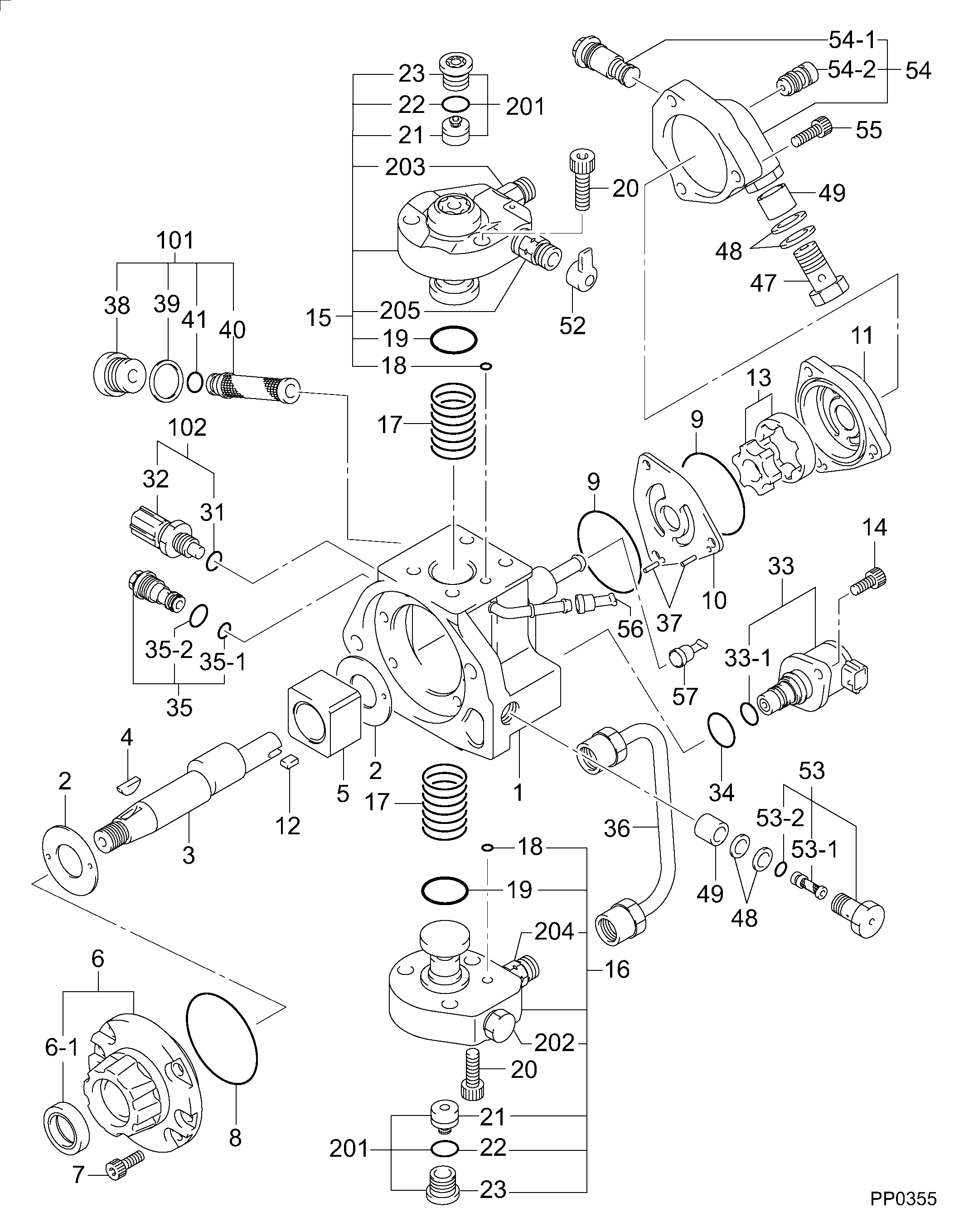
Components :
Scheme #.#:
№
Qty
Part num
Name
Remarks
Manufacture num
000
[01]
29400-01440
PUMP ASSY, SUPPLY
HP3 #
22100-E0540-A
HINO
Include in ##:
29400-01440
as PUMP ASSY, SUPPLY
Cross reference number
Part num
Firm num
Firm
Name
29400-01440
22100-E054
PUMP ASSY, SUPPLY
2940001440
22100-E0540-A
HINO
PUMP ASSY, SUPPLY
Information:
2. Remove bolts (1) from the adapter. Loosen turbocharger compressor housing clamp (2), and rotate turbocharger tube (3) out of the way of the aftercooler housing. 3. Put identification marks on the bolts which hold the aftercooler cover in position for installation purposes. Remove bolts (4) that hold the aftercooler cover to the aftercooler housing. Remove aftercooler cover (5). 4. Remove four bolts (6), elbow (7), the two adapters and pipe (8). 5. Remove four bolts (9), elbow (10) and two adapters (11). 6. Remove aftercooler core (12) from aftercooler housing (13). 7. Remove O-ring seals (14) and gaskets (15) if necessary.Install Aftercooler Core
1. Clean and inspect all parts. Make a replacement of all parts that are worn or damaged. Lubricate all O-ring seals with clean engine oil at assembly. 2. Install O-ring seals (1). Fasten gaskets (2) to both sides of the aftercooler core flange with 5H2471 Cement. 3. Put aftercooler core (3) in position in the aftercooler housing with the end that has the identification "Jacket Water, Fresh Air" toward the water inlet end of the aftercooler housing. 4. Install cover (4) on the aftercooler housing. Be sure to install the long bolts in the thru bolt holes.
To prevent damage to the aftercooler core, tighten the bolts that hold the aftercooler core before tightening the bolts that hold the adapters.
5. Tighten the aftercooler core cover bolts to a torque of 25 7 N m (18 5 lb.ft.). Tighten the bolts again after engine is operated to a torque of 25 7 N m (18 5 lb.ft.). 6. Install gasket (5) and adapter (6) on the aftercooler housing. 7. Install adapter (7) on adapter (6). 8. Put O-ring seals (8) on pipe (9), and install pipe (9) into elbow (10). 9. Install elbow (11) on pipe (9). Put gasket (12) in position between elbow (11) and adapter (7), and fasten the elbow to aftercooler housing with four bolts. 10. Install gasket (13) and adapter (14) on the aftercooler housing. 11. Install adapter (15) on adapter (14). 12. Put O-ring seal (16) in position on tube (17), and install elbow (18) on tube (17). Put gasket (19) in position between elbow (18) and adapter (15), and fasten the elbow to the aftercooler housing with four bolts. 13. Rotate turbocharger tube (20) into position. Place a gasket between the aftercooler housing and adapter, and install the four bolts and nuts that hold it.14. Tighten turbocharger clamp nut (21) to a torque of 18 3 N m (13 2 lb.ft.). Lightly hit all around the clamp with a soft faced hammer, and tighten the clamp nut again to the same torque value.15. Fill the engine with coolant to the correct level. See the Maintenance Guide.