Rating:
Information pump assy, supply Denso
Compare Prices: .
As an associate, we earn commssions on qualifying purchases through the links below

Zachager 1PC Fuel Injection Pump 294000-1133 8-98081772-3 for Isuzu Engine 4HK1
Zachager PART NUMBER: 294000-1133 8-98081772-3 || APPLICATION: for Isuzu Engine 4HK1 || Fuel Injection Pump works absolutely well since every item we have executed a strict quality test prior shipping.Plug and play, easy to install, you could use it directly. || Please check the specification carefully to ensure you get what you want.Our products are made of High quality durability material and excellent crafts.Proper use of the product can make the product have a longer service life || Please rest assured to buy our products, we will deliver the products to you faster.
Zachager PART NUMBER: 294000-1133 8-98081772-3 || APPLICATION: for Isuzu Engine 4HK1 || Fuel Injection Pump works absolutely well since every item we have executed a strict quality test prior shipping.Plug and play, easy to install, you could use it directly. || Please check the specification carefully to ensure you get what you want.Our products are made of High quality durability material and excellent crafts.Proper use of the product can make the product have a longer service life || Please rest assured to buy our products, we will deliver the products to you faster.

Fuel Injection Pump 294000-1133 8-98081772-3 For Isuzu Engine 4HK1
oiasdfhjdg Product name:Fuel Injection Pump || Part Number:294000-1133 8-98081772-3 || APPlication:For Isuzu Engine 4HK1 || 1.Please carefully compare the OE numbers before purchasing the product to match your original parts and avoid wasting your valuable time. || 2.Please ensure to provide us with the correct, accurate, and detailed delivery address and contact information
oiasdfhjdg Product name:Fuel Injection Pump || Part Number:294000-1133 8-98081772-3 || APPlication:For Isuzu Engine 4HK1 || 1.Please carefully compare the OE numbers before purchasing the product to match your original parts and avoid wasting your valuable time. || 2.Please ensure to provide us with the correct, accurate, and detailed delivery address and contact information

Diesel Fuel Injector Pump 294000-1133 Compatible With Isuzu 8-98081772-1 2940001133
HXYAIEOGD Ensure the continuous and stable operation of the engine. || The installation procedure is simple. || Ensure OE number before placing order. || The warranty period is 12 months. || 1 piece jet pump
HXYAIEOGD Ensure the continuous and stable operation of the engine. || The installation procedure is simple. || Ensure OE number before placing order. || The warranty period is 12 months. || 1 piece jet pump
You can buy:

Include in ##:
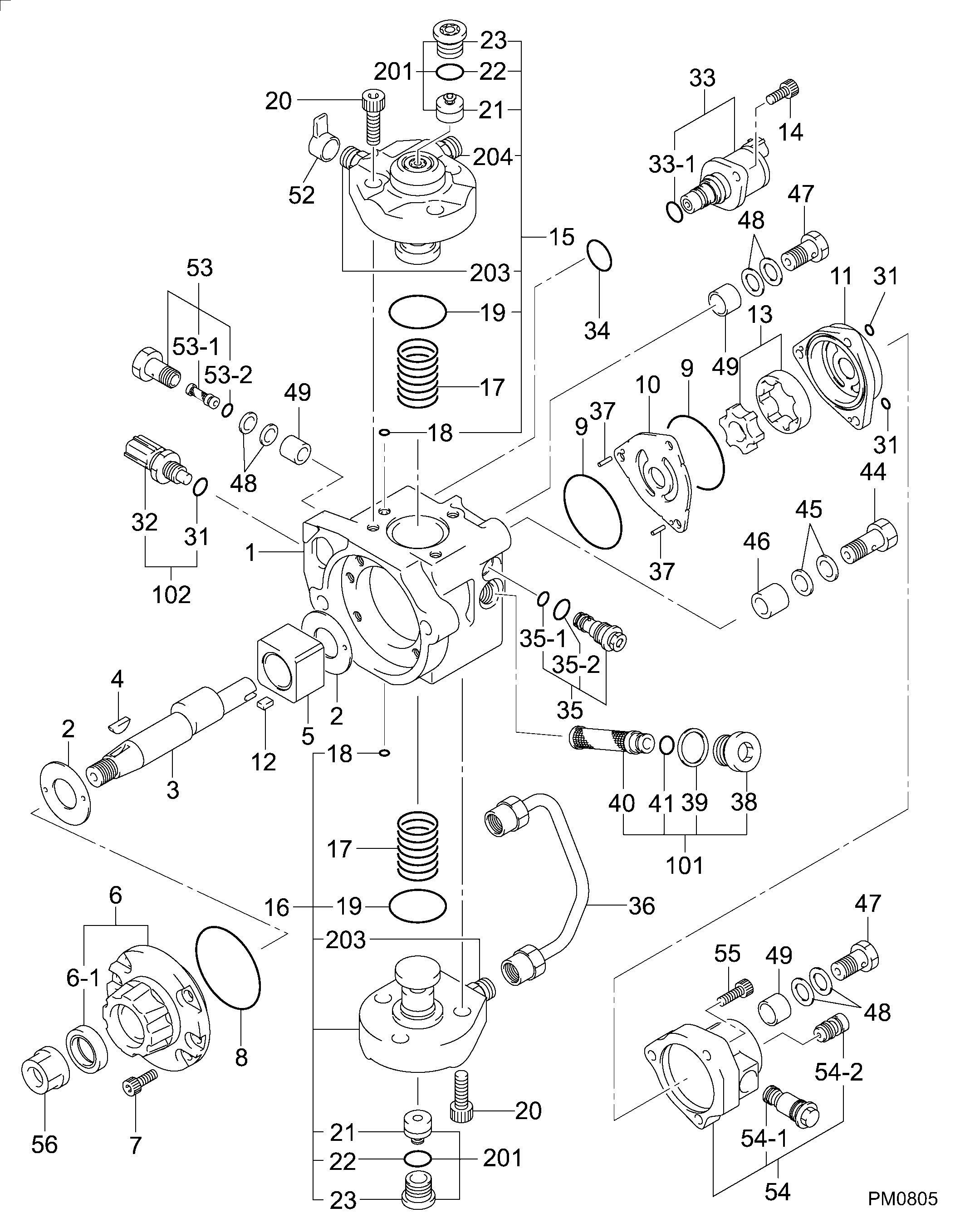
Cross reference number
Part num
Firm num
Firm
Name
29400-01133
8-98081772
PUMP ASSY, SUPPLY
Information:
2. Remove clamp (2) from water sleeves (1) in each cylinder head. Push the water sleeves into the timing gear cover with tool (A) and a screwdriver. 3. Remove bolt (3) from the bracket on the dipstick tube. 4. Remove bolts (4) and stud (5) from the heads.
Make sure the fuel injection nozzles are removed before the cylinder heads are removed. The fuel injection nozzles go through the cylinder heads and the nozzle tips can be broken off if the nozzles are not removed from the heads.
5. Install tooling (B) and fasten a hoist. Remove bolts (7), cylinder head (6) and the gasket. The weight of the cylinder head is 54 kg (120 lb.).Install Cylinder Heads
1. Clean the contact surfaces of the cylinder head and cylinder block. Make sure the surfaces are clean and dry. Install a new cylinder head gasket. Clean the bore in the cylinder head for the water sleeves. Put oil on the seals on the water sleeves.2. Install tooling (B) in the cylinder head. Fasten a hoist and put the cylinder head in position on the cylinder block.3. Put 6V4876 Molykote Lubricant on the bolt threads and install the bolts that hold the cylinder head in their correct location. Tighten the bolts in the cylinder head according to the HEAD BOLT TORQUE CHART.
The higher cylinder head bolt torque may be used on earlier engines ONLY if the bolts are replaced with the later higher strength bolts (seven dash marks on the bolt head). If the earlier bolts are tightened to the later torque specification, they may yield (stretch) and lose their clamping force.
4. Install water sleeve into cylinder head with tool (A). Install the clamp on the water sleeves.5. Fill the cooling system with coolant to the correct level. end by:a) install fuel injection nozzlesb) install rocker shafts and push rodsc) install valve coversd) install air inlet manifolde) install exhaust manifold
Illustration 1. Bolt head identification.Disassemble Cylinder Heads
start by: a) remove cylinder heads1. Fasten a hoist and put the cylinder head in position on tool (A). Use adapter plates (1) from tooling (A) to hold the head in place. 2. Put the valve springs under compression with tool (C). 3. Remove the locks from the valves. Earlier engines have an inner valve spring. Later engines have only one valve spring and a spacer instead of inner spring.4. Remove tool (C), retainer, spring, washer and valve from the cylinder head. Put identification on the valve as to its location in the cylinder head. 5. Check the valve spring force with tool (B). For the correct spring force, see the subject VALVES in SPECIFICATIONS.6. Do Steps 2 through 5 for the remainder of the valves.7. Remove the valve seat inserts with tooling (D). The valve guides are part of the cylinder head. Measure the bore in each valve guide 19.0 mm (.75 in.) from the outside edge on both ends of each valve guide. The bore must be 9.512 0.013 mm (.3745 .0005 in.). The