Rating:
Information pump assy, supply Denso
Compare Prices: .
As an associate, we earn commssions on qualifying purchases through the links below

Fuel injection Pump 294000-0980 16625AA020 for Subaru Engine EE20Z
AUCALIWI Part number:294000-0980,16625AA020 || Application:for Subaru Engine EE20Z
AUCALIWI Part number:294000-0980,16625AA020 || Application:for Subaru Engine EE20Z

Fuel injection Pump 294000-0980 16625AA020 for Subaru Engine EE20Z
ADPelcote Part number:294000-0980 || Applications:for Subaru Engine EE20Z
ADPelcote Part number:294000-0980 || Applications:for Subaru Engine EE20Z

$1,748.68
01 Apr 2024
CN: QYWD
16625AA020 294000-0980 Fuel injection Pump Compatible for Subaru Engine EE20Z
TUWODE Part Number: 16625AA020 || Part Name: Fuel Injection Pump || Application:for Subaru Engine EE20Z || Enhanced Fuel Efficiency: The fuel injection pump provides precise control over the amount and timing of fuel injection, ensuring that fuel enters the combustion chamber at the optimal moment to maximize fuel efficiency. || Improved engine performance: By delivering a more precise amount of fuel, the fuel injection pump contributes to smooth engine operation, increased power output and responsiveness.
TUWODE Part Number: 16625AA020 || Part Name: Fuel Injection Pump || Application:for Subaru Engine EE20Z || Enhanced Fuel Efficiency: The fuel injection pump provides precise control over the amount and timing of fuel injection, ensuring that fuel enters the combustion chamber at the optimal moment to maximize fuel efficiency. || Improved engine performance: By delivering a more precise amount of fuel, the fuel injection pump contributes to smooth engine operation, increased power output and responsiveness.
Include in ##:
Cross reference number
Part num
Firm num
Firm
Name
29400-00984
16625AA020
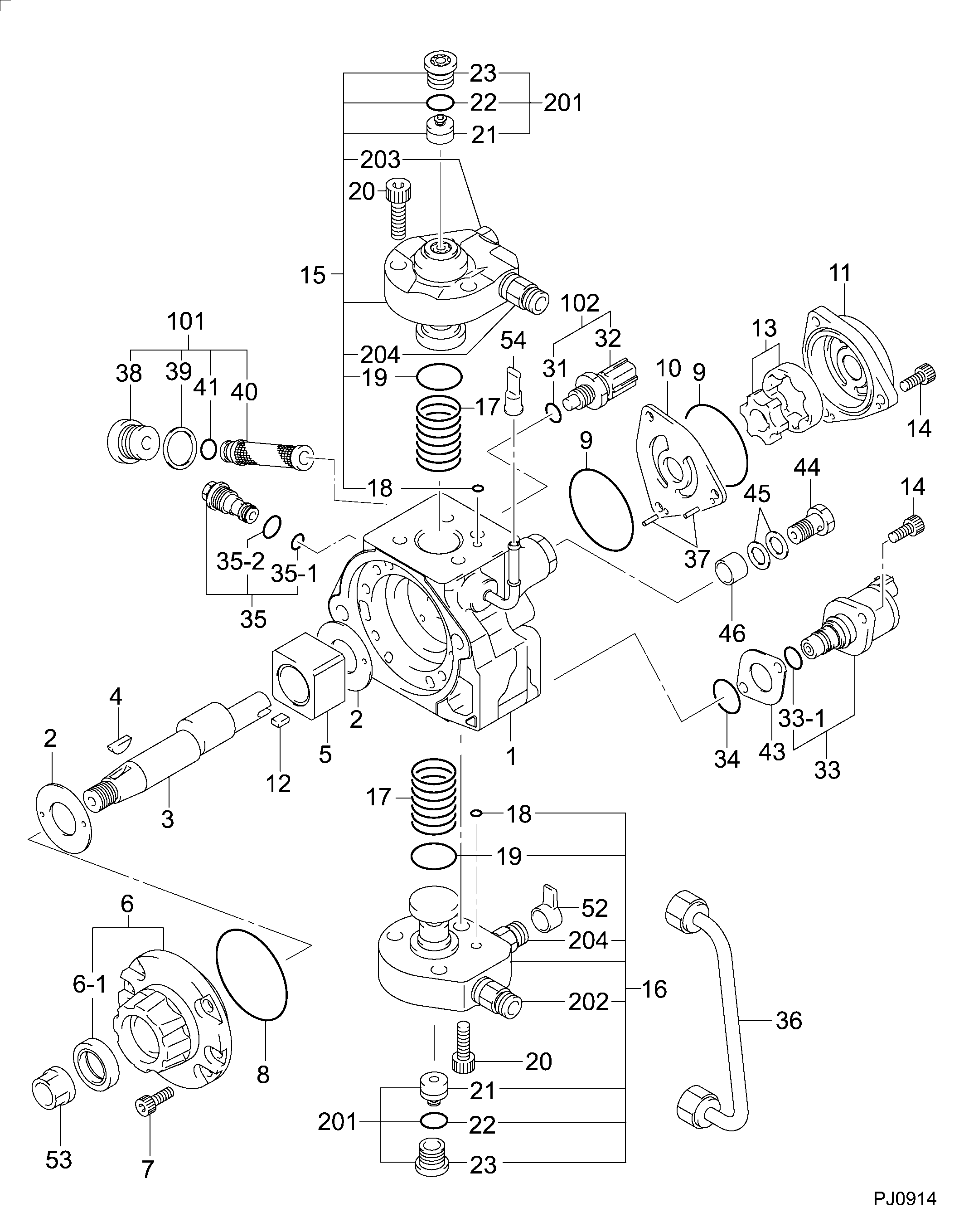
PUMP ASSY, SUPPLY
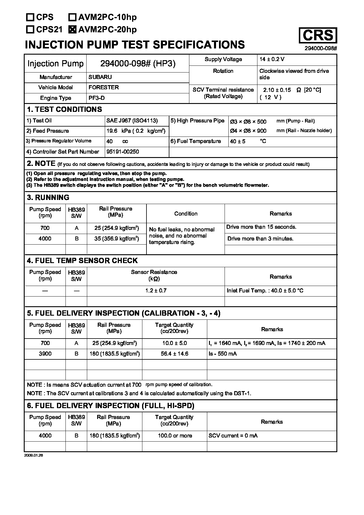
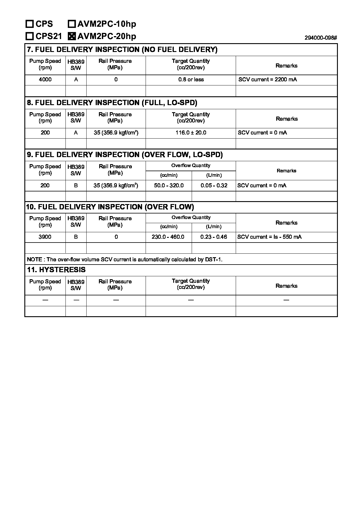
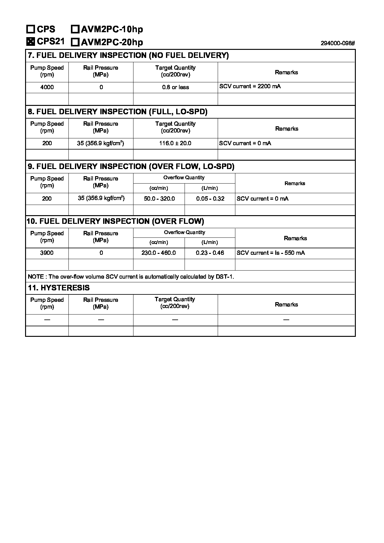
Test Calibration Data:
01EN098100
16625AA020
01EN098100
16625AA020
02EN098100
16625AA020

02EN098100
16625AA020
2940000980
16625AA020


Information:
preparatory steps: a) remove rocker shaft assemblyb) remove water temperature regulator1. Disconnect the fuel ratio control sensing line (1). Remove the sensing line clamp bolt (2). 2. Disconnect the turbocharger oil supply line (3) and the oil drain line (4).3. Remove the fuel injection lines (5) and install protective caps.4. Disconnect the air compressor water return line (8). 5. Remove the retaining bolts (7) and the fan drive mounting bracket (6).6. Remove the cylinder head retaining bolts. Attach a hoist and remove the cylinder head assembly-weight 240 lbs. (109,1 kg).Install Cylinder Head Assembly
1. Thoroughly clean the sealing surfaces of the cylinder head and cylinder block. Position a new head gasket on the engine and install the cylinder head assembly.2. Install the push rods and rocker shaft assembly.3. Coat the threads of the cylinder head retaining bolts with 4S9416 Anti-Seize Compound. Install bolts and washers, and tighten them in the following sequence: 1 - Tighten all numbered bolts in numerical order to 115 lb. ft. (15,9 mkg).2 - Retighten all numbered bolts in numerical order to 175 5 lb. ft. (24,2 0,7 mkg).3 - Finally, retighten all numbered bolts (hand torque only) in numerical order to 175 5 lb. ft. (24,2 0,7 mkg).4 - Tighten all lettered bolts in alphabetical order to 22 lb. ft. (3,0 mkg).5 - Retighten all lettered bolts in alphabetical order to 32 5 lb. ft. (4,4 0,7 mkg).6 - Finally, retighten all lettered bolts (hand torque only) in alphabetical order to 32 5 lb. ft. (4,4 0,7 mkg).4. Adjust the inlet and exhaust valve clearance as covered in INSTALL ROCKER SHAFT ASSEMBLY AND PUSH RODS.5. Connect the air compressor water return line.6. Install the fuel lines and tighten the retaining nuts to 30 5 lb. ft. (4,1 0,7 mkg).7. Connect the turbocharger oil supply line and the oil drain line.8. Connect the fuel ratio control sensing line and install the sensing line clamp bolt.9. Install the fan drive mounting bracket and retaining bolts.concluding steps: a) install water temperature regulatorb) install valve cover
1. Thoroughly clean the sealing surfaces of the cylinder head and cylinder block. Position a new head gasket on the engine and install the cylinder head assembly.2. Install the push rods and rocker shaft assembly.3. Coat the threads of the cylinder head retaining bolts with 4S9416 Anti-Seize Compound. Install bolts and washers, and tighten them in the following sequence: 1 - Tighten all numbered bolts in numerical order to 115 lb. ft. (15,9 mkg).2 - Retighten all numbered bolts in numerical order to 175 5 lb. ft. (24,2 0,7 mkg).3 - Finally, retighten all numbered bolts (hand torque only) in numerical order to 175 5 lb. ft. (24,2 0,7 mkg).4 - Tighten all lettered bolts in alphabetical order to 22 lb. ft. (3,0 mkg).5 - Retighten all lettered bolts in alphabetical order to 32 5 lb. ft. (4,4 0,7 mkg).6 - Finally, retighten all lettered bolts (hand torque only) in alphabetical order to 32 5 lb. ft. (4,4 0,7 mkg).4. Adjust the inlet and exhaust valve clearance as covered in INSTALL ROCKER SHAFT ASSEMBLY AND PUSH RODS.5. Connect the air compressor water return line.6. Install the fuel lines and tighten the retaining nuts to 30 5 lb. ft. (4,1 0,7 mkg).7. Connect the turbocharger oil supply line and the oil drain line.8. Connect the fuel ratio control sensing line and install the sensing line clamp bolt.9. Install the fan drive mounting bracket and retaining bolts.concluding steps: a) install water temperature regulatorb) install valve cover