Rating:
Information pump assy, supply Denso
Product
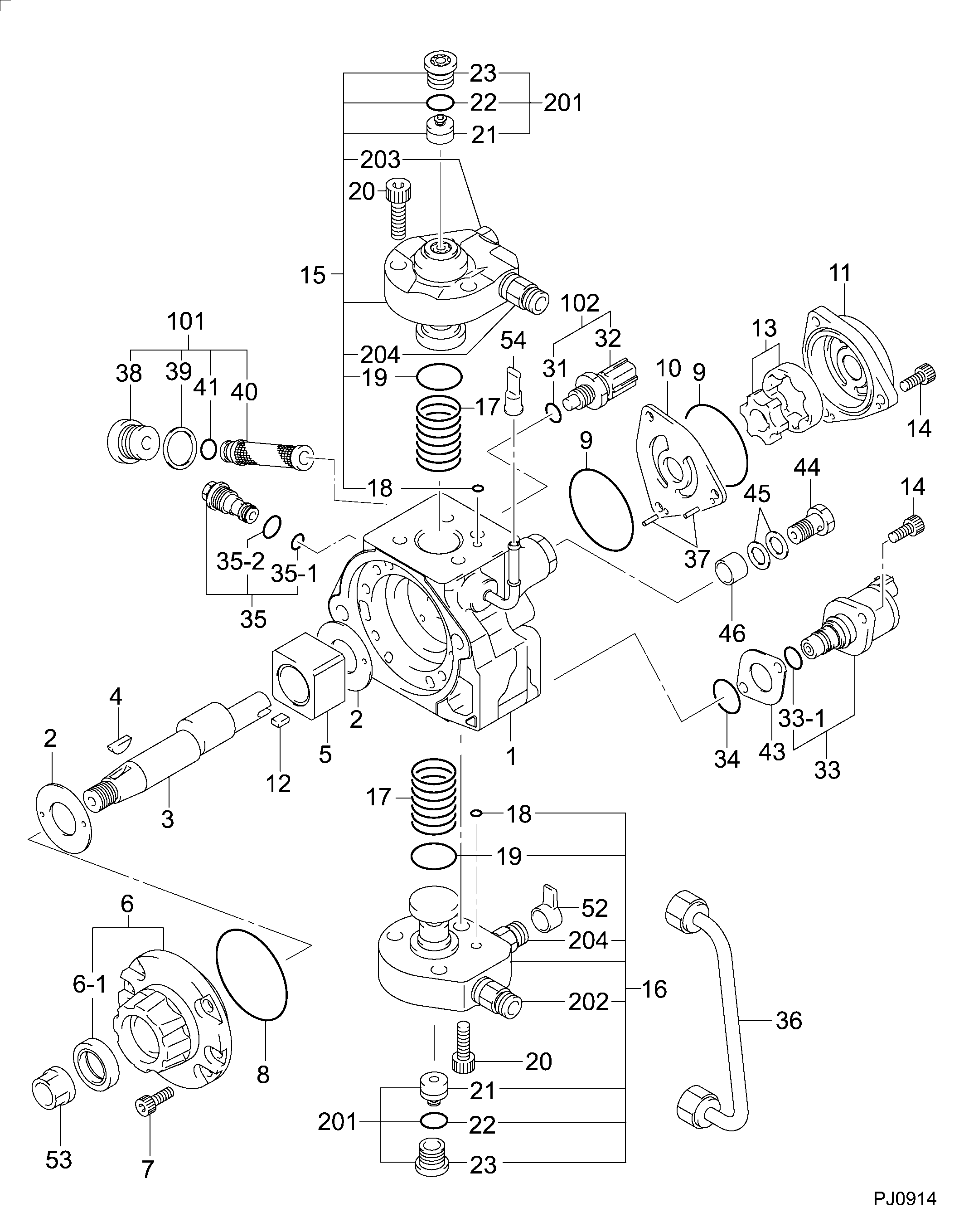
Fuel Injection Pump
Vehicle engine
FORESTER SHD
Engine
SHD
Serial start-end
0807-
Info
Injector Nozzle
SUBARU
PUMP ASSY, SUPPLY
HA
- #..NEW PARTS ARE INTERCHANGEABLE WITH OLD ONE,
- IF NO.3,4 ARE CHANGED AT THE SAME TIME.
Compare Prices: .
As an associate, we earn commssions on qualifying purchases through the links below

Fuel injection Pump 294000-0980 16625AA020 for Subaru Engine EE20Z
AUCALIWI Part number:294000-0980,16625AA020 || Application:for Subaru Engine EE20Z
AUCALIWI Part number:294000-0980,16625AA020 || Application:for Subaru Engine EE20Z

Fuel injection Pump 294000-0980 16625AA020 for Subaru Engine EE20Z
ADPelcote Part number:294000-0980 || Applications:for Subaru Engine EE20Z
ADPelcote Part number:294000-0980 || Applications:for Subaru Engine EE20Z

$1,748.68
01 Apr 2024
CN: QYWD
16625AA020 294000-0980 Fuel injection Pump Compatible for Subaru Engine EE20Z
TUWODE Part Number: 16625AA020 || Part Name: Fuel Injection Pump || Application:for Subaru Engine EE20Z || Enhanced Fuel Efficiency: The fuel injection pump provides precise control over the amount and timing of fuel injection, ensuring that fuel enters the combustion chamber at the optimal moment to maximize fuel efficiency. || Improved engine performance: By delivering a more precise amount of fuel, the fuel injection pump contributes to smooth engine operation, increased power output and responsiveness.
TUWODE Part Number: 16625AA020 || Part Name: Fuel Injection Pump || Application:for Subaru Engine EE20Z || Enhanced Fuel Efficiency: The fuel injection pump provides precise control over the amount and timing of fuel injection, ensuring that fuel enters the combustion chamber at the optimal moment to maximize fuel efficiency. || Improved engine performance: By delivering a more precise amount of fuel, the fuel injection pump contributes to smooth engine operation, increased power output and responsiveness.
You can buy:

Include in ##:
Cross reference number
Part num
Firm num
Firm
Name
29400-00980
16625AA020
SUBARU
PUMP ASSY, SUPPLY
2940000980
16625AA020
SUBARU
PUMP ASSY, SUPPLY
2940000980
16625AAS020
SUBARU
PUMP ASSY SUPPLY
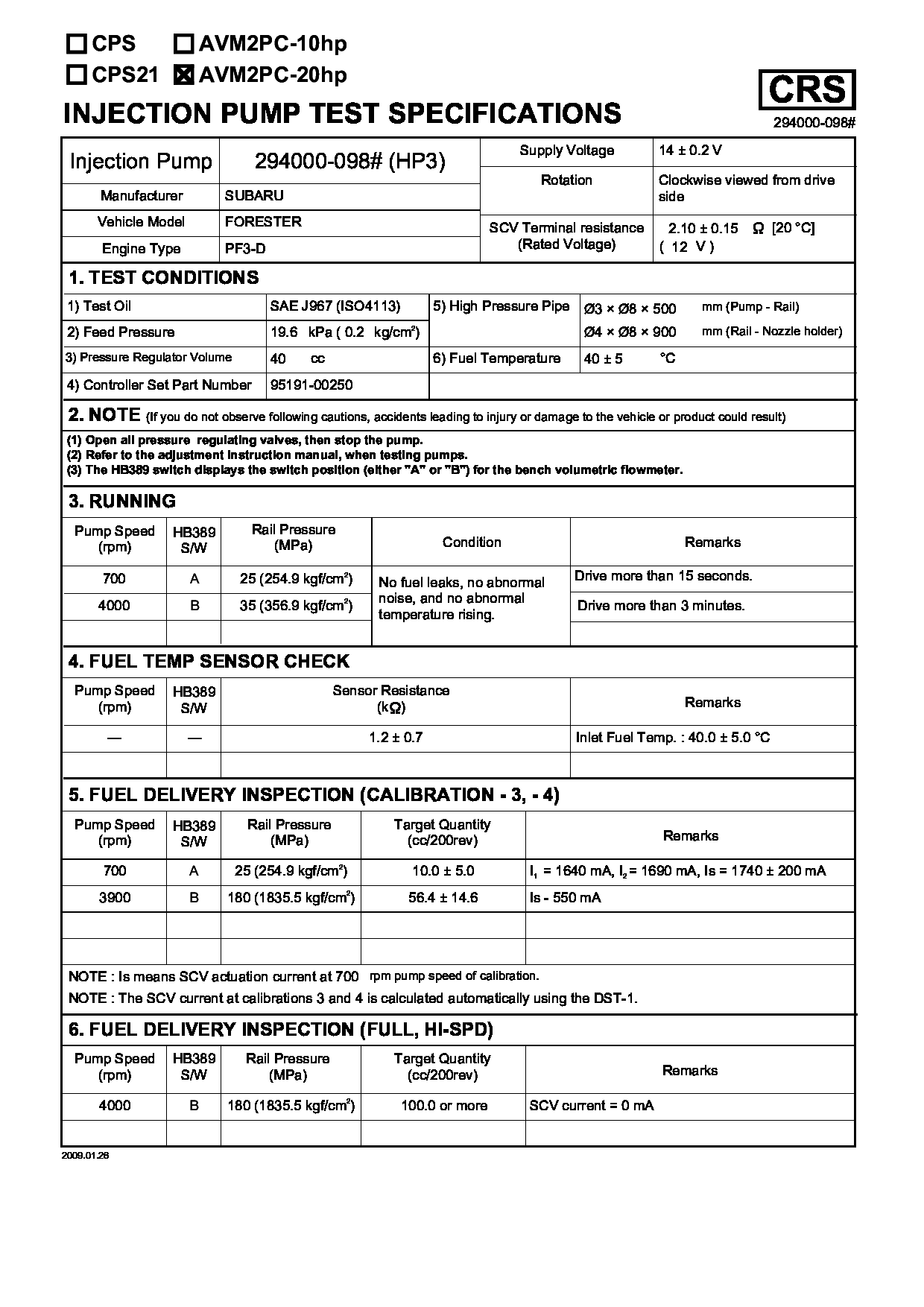
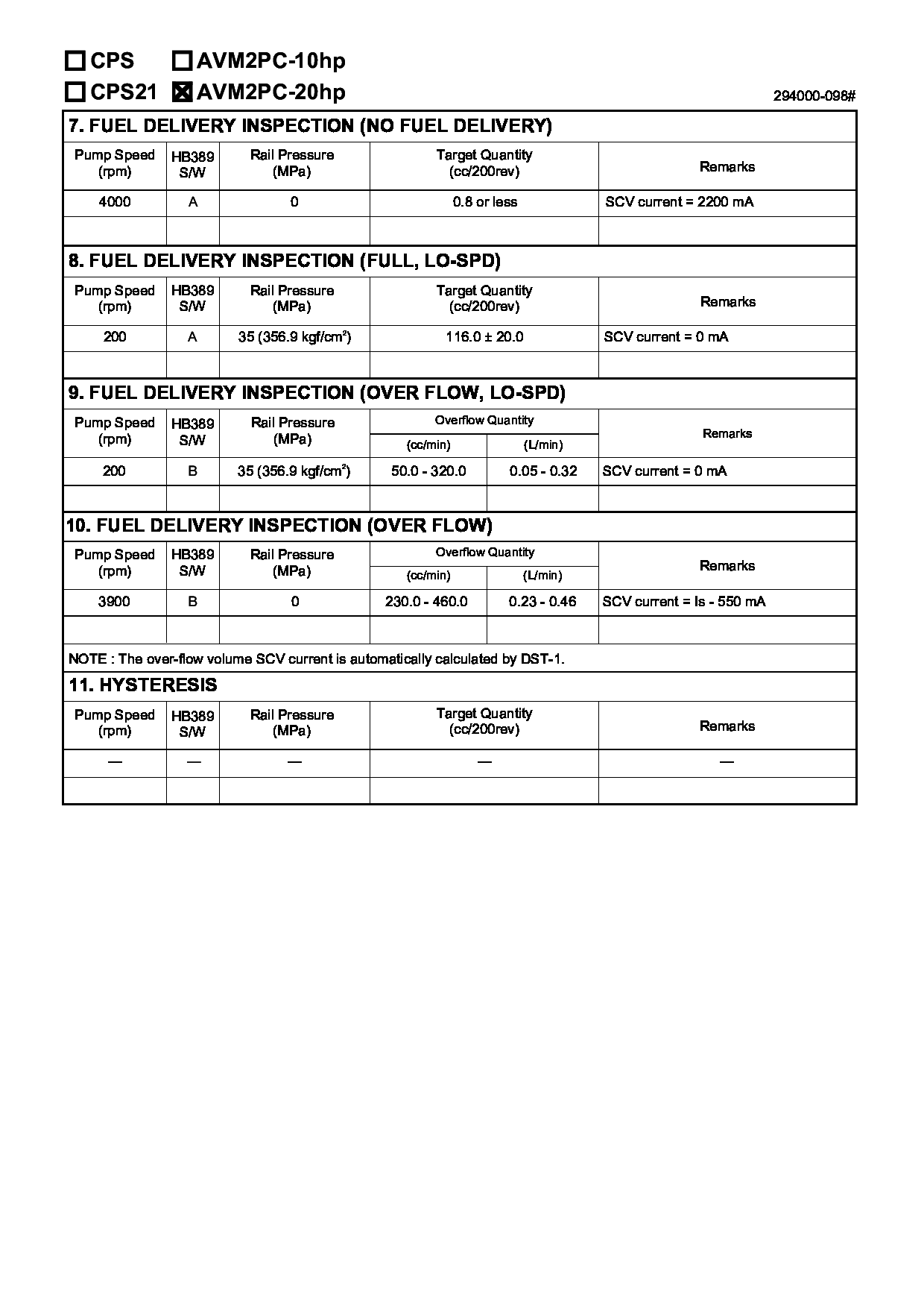
Test Calibration Data:
01EN098100
16625AA020
01EN098100
16625AA020
Information:
preparatory steps: a) remove timing gear coverb) remove fuel injection pump housing and governorc) remove fuel transfer pump 1. Disconnect the accessory drive oil supply line (1) and the fuel drain line (2). Remove the fuel priming pump.2. Remove the accessory drive shaft gear retaining nut, washer, and sleeve. 3. Using tool (A), remove the accessory drive gear. 4. Remove four retaining bolts (3), two locks and retainer (4).5. Remove the accessory drive housing.6. Remove the accessory drive shaft and bearing as a unit from the housing. 7. Using tool (B), remove bearing (5).Install Accessory Drive Shaft
1. Heat the accessory drive shaft bearing to 300°F (149°C) and install the bearing on the shaft. 2. Install the accessory drive shaft and bearing (1) in the housing.3. Install the accessory drive housing. 4. Install the retainer, locks and retaining bolts.5. Locate top center (TC) compression stroke for No. 1 piston. See LOCATING TOP CENTER COMPRESSION POSITION FOR No. 1 PISTON in TESTING AND ADJUSTING. 6. Rotate the accessory drive shaft until tool (A) can be installed. 7. Install the accessory drive shaft sleeve, drive gear, conical washer and nut. Install the conical washer on the drive shaft with the O.D. in contact with the gear. Tighten the retaining nut (2) to 100 10 lb. ft. (13,8 1,4 mkg).8. Connect the fuel drain line and the oil supply line. Install the fuel priming pump.concluding steps: a) install fuel transfer pumpb) install fuel injection pump housing and governorc) install timing gear cover
1. Heat the accessory drive shaft bearing to 300°F (149°C) and install the bearing on the shaft. 2. Install the accessory drive shaft and bearing (1) in the housing.3. Install the accessory drive housing. 4. Install the retainer, locks and retaining bolts.5. Locate top center (TC) compression stroke for No. 1 piston. See LOCATING TOP CENTER COMPRESSION POSITION FOR No. 1 PISTON in TESTING AND ADJUSTING. 6. Rotate the accessory drive shaft until tool (A) can be installed. 7. Install the accessory drive shaft sleeve, drive gear, conical washer and nut. Install the conical washer on the drive shaft with the O.D. in contact with the gear. Tighten the retaining nut (2) to 100 10 lb. ft. (13,8 1,4 mkg).8. Connect the fuel drain line and the oil supply line. Install the fuel priming pump.concluding steps: a) install fuel transfer pumpb) install fuel injection pump housing and governorc) install timing gear cover