Rating:
Information pump assy, supply Denso
Product
Fuel Injection Pump
Vehicle engine
TRUCK N04C
Engine
N04C
Serial start-end
0710-
Info
Injector Nozzle
Compare Prices: .
As an associate, we earn commssions on qualifying purchases through the links below

Aftermarket Fuel Injection Pump 294000-0963 22100-E0243 Fit Intended For Engine N04C Truck 195
Generic Motorcycle Parts || Heavy Equipment Parts || Spare Parts || Fuel Systems
Generic Motorcycle Parts || Heavy Equipment Parts || Spare Parts || Fuel Systems

Fuel Injection Pump 294000-0963 22100-E0243 for Hino Engine N04C Truck 195
100% Apollo part number:294000-0963 22100-E0243 || application: for Hino Engine N04C Truck 195
100% Apollo part number:294000-0963 22100-E0243 || application: for Hino Engine N04C Truck 195

$629.00
09 Dec 2024
CN: qian cheng
Fuel Injection Pump 294000-0963 22100-E0243 for Hino Engine N04C Truck 195
ADPelcote Part number:294000-0963 || Applications:for Hino Engine N04C Truck 195
ADPelcote Part number:294000-0963 || Applications:for Hino Engine N04C Truck 195
You can buy:

Include in ##:
Cross reference number
Part num
Firm num
Firm
Name
29400-00963
22100-E024
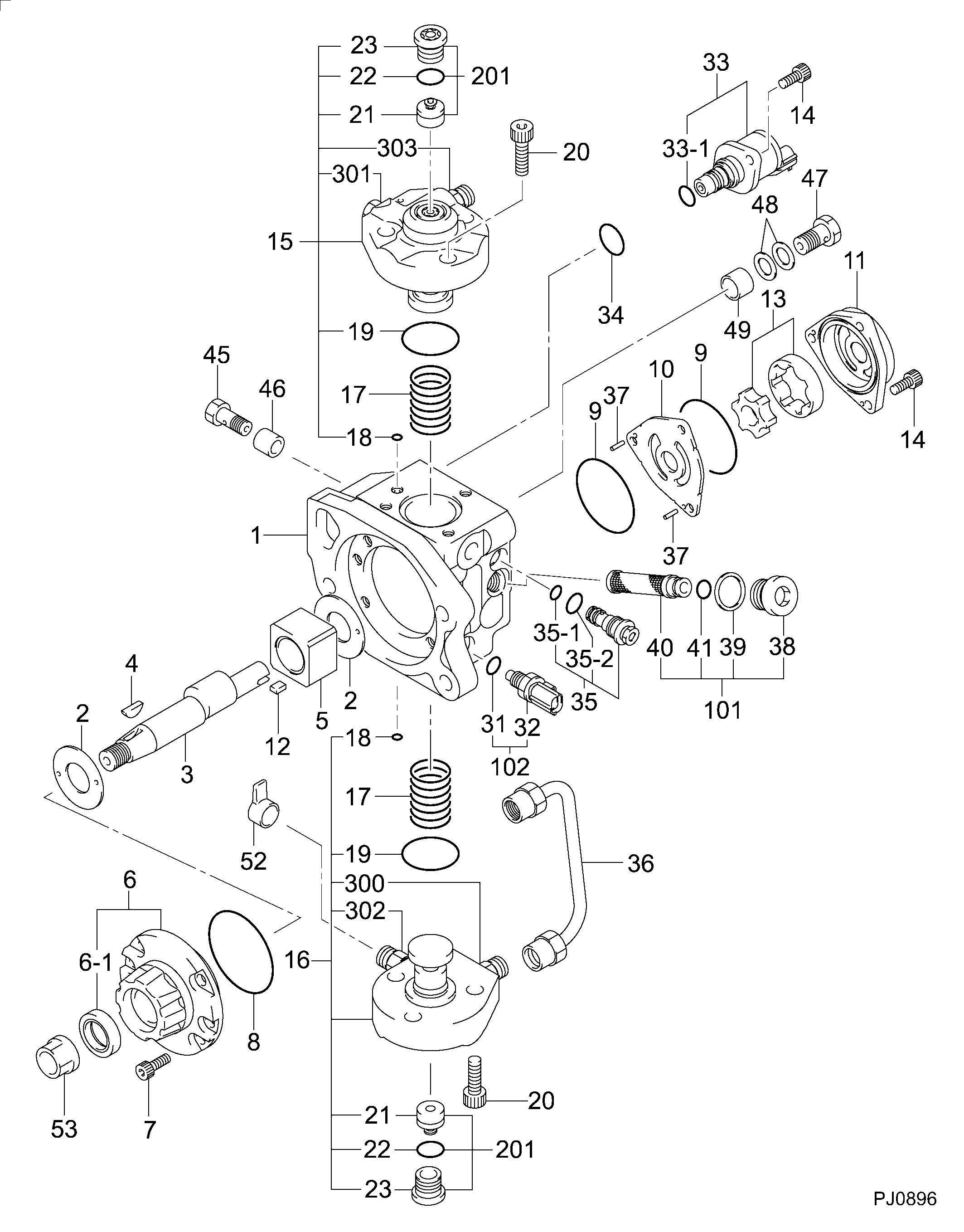
PUMP ASSY, SUPPLY
Information:
1. Remove the seat retaining ring (1) and pin (2). 2. Remove the seat (3), bolt (4), washers (5) and spring (6).3. Remove the sleeve and bearing assembly from the cylinder and weight assemblies. 4. Remove the retaining ring (7) from sleeve (8).5. Remove bearing (9) and races (10) from sleeve (8). 6. Remove the valve (11) from piston (12).7. Remove the cylinder-to-weight assembly retaining ring (13).8. Remove the weight assembly (14).9. Remove piston (12) and sleeve (15) from the cylinder (16).10. Remove the O-ring seal from the sleeve (15). 11. Remove the speed limiter plug (17), spring (18), and plunger (19) from the governor housing.12. Remove the high idle screw (21) and low idle screw (20). 13. Remove the lever assembly-to-shaft assembly retaining bolt (23) and lock.14. Remove the shaft assembly (22) and lever assembly (24) from governor housing.15. Remove the seal from governor housing. 16. Remove two retaining bolts (25) and lock. Remove the lever (26) and shaft (27) from idle screw housing.17. Remove two seals and bearing from idle screw housing.Assemble Governor
1. Using tool (A) install the inner seal in idle screw housing with spring side of seal facing the driver. Install bearing and outer seal with lip of the seal toward the inside of the housing. Lubricate lip of seal with clean SAE 30 engine oil.2. Position the shaft and lever in the idle screw housing. Install the retaining bolts and lock. 3. Using tool (A), install the seal in the governor housing with spring side of seal toward inside of governor housing. Lubricate lip of seal with clean SAE 30 engine oil.4. Position the lever assembly and shaft in the governor housing. Install the retaining bolt and lock.5. Install the high and low idle screws in the governor housing.6. Install the speed limiter plug, spring, and plunger in the governor housing. 7. Install the O-ring seal (3) on sleeve (4).8. Install piston (2) and sleeve (4) in the cylinder (1). 9. Position the weight assembly (6) on cylinder (7), and install retaining ring (5). 10. Install the valve (9) in piston (10).11. Install the bearing and races in sleeve. Install retaining ring. Install the sleeve and bearing assembly (8) on valve (9). 12. Position the seat (12), bolt (11), washers and spring on the valve (9). Install the retaining pin (14) and retaining ring (13).concluding step: a) connect governor to fuel injection pump housing
1. Using tool (A) install the inner seal in idle screw housing with spring side of seal facing the driver. Install bearing and outer seal with lip of the seal toward the inside of the housing. Lubricate lip of seal with clean SAE 30 engine oil.2. Position the shaft and lever in the idle screw housing. Install the retaining bolts and lock. 3. Using tool (A), install the seal in the governor housing with spring side of seal toward inside of governor housing. Lubricate lip of seal with clean SAE 30 engine oil.4. Position the lever assembly and shaft in the governor housing. Install the retaining bolt and lock.5. Install the high and low idle screws in the governor housing.6. Install the speed limiter plug, spring, and plunger in the governor housing. 7. Install the O-ring seal (3) on sleeve (4).8. Install piston (2) and sleeve (4) in the cylinder (1). 9. Position the weight assembly (6) on cylinder (7), and install retaining ring (5). 10. Install the valve (9) in piston (10).11. Install the bearing and races in sleeve. Install retaining ring. Install the sleeve and bearing assembly (8) on valve (9). 12. Position the seat (12), bolt (11), washers and spring on the valve (9). Install the retaining pin (14) and retaining ring (13).concluding step: a) connect governor to fuel injection pump housing